z/OS Communications Server: SNA Network Implementation Guide
Previous topic | Next topic | Contents | Contact z/OS | Library | PDF


Defining a link-attached NCP

z/OS Communications Server: SNA Network Implementation Guide
SC27-3672-01

Figure 1 illustrates a link-attached NCP (NCP2). The connection between a channel-attached and a link-attached NCP is defined in each of the NCP subarea nodes. You define each end of the connection in each NCP using a LINE definition statement for the link and a PU definition statement for the link station.

Figure 1. Defining, loading, and activating a link-attached NCP
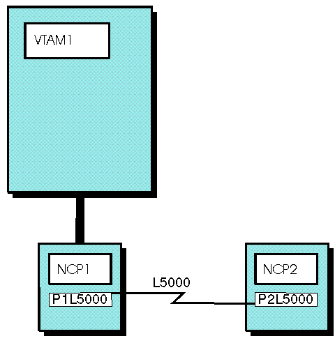
Defining, loading, and activating a link-attached NCP
The following example illustrates the definitions (at the channel-attached NCP, NCP1) for the link and link station when using a nonswitched SDLC link to the link-attached NCP subarea node:
*----------------------------------------------------------------------
*  256 KILOBYTE LINK
*----------------------------------------------------------------------
G5INN    GROUP ACTIVTO=120,                ACTIVATE TIME OUT VALUE
               DIAL=NO,                    NONSWITCHED LINK
               LNCTL=SDLC,                 SDLC LINE CONTROL
               REPLYTO=(10.0,15.0),        REPLAY TIMEOUT VALUES
               ⋮
               ISTATUS=ACTIVE              VTAM STATUS
*
L5000    LINE  ADDRESS=(000,FULL),         LINE ADDRESS — FULL DUPLEX
               SPEED=245760,               LINK SPEED
               HISPEED=YES,                HIGH SPEED LINK
               MONLINK=YES,                SDLC MONITOR MODE ON
               IPL=YES,                    ACCEPT IPL REQUEST
               ⋮
               MODULO=128,                 MODULO COUNT = 128
               PAUSE=(1.0,1.0),            PRIMARY AND SECONDARY PAUSE
               RETRIES=(3,12,5),           RETRY VALUES
               SDLCST=(PRIM,SEC),          PRIMARY AND SECONDARY CHARACTERISTICS
               ISTATUS=ACTIVE              VTAM STATUS
*
P1L5000  PU    ANS=CONTINUE,               AUTOMATIC NETWORK SHUTDOWN
               MAXOUT=127,                 FRAMES PRIOR TO LINK-LEVEL REPLY
               ⋮
               PUTYPE=4,                   TYPE 4 — NCP CONNECTION
               TGN=7,                      TRANSMISSION GROUP NUMBER
               ISTATUS=ACTIVE              VTAM STATUS

To load and activate the link-attached NCP:

  1. Specify the link station name of the channel-attached NCP (in the example, P1L5000) in the RNAME operand of either the PCCU definition statement for the link-attached NCP (NCP2) or the VARY ACT command.
    On the PCCU Definition Statement for NCP2:
     
    PCCU  SUBAREA=1,
    ⋮
          LOADSTA=P1L5000,
          RNAME=P1L5000,
    ⋮
    On the VARY ACT Operator Command:
     
    VARY ACT,ID=NCP2,LOAD=YES,RNAME=P1L5000
  2. Define the characteristics of the link. The NCP subarea nodes exchange information over the link using the XID process. The subarea node with the higher subarea number performs the role of the primary and performs the polling unless this role relationship is predefined. The characteristics associated with the link, depending on primary or secondary role, must be defined using the SDLCST and GROUP definition statements in the NCP subarea nodes.

Cross-subarea links can be directly or indirectly activated and deactivated. For information about using links, see Activating links and Deactivating links.

Go to the previous page Go to the next page


Copyright IBM Corporation 1990, 2014