 z/OS Communications Server: SNA Network Implementation Guide
 z/OS Communications Server: SNA Network Implementation Guide
|
Previous topic |
Next topic |
Contents |
Contact z/OS |
Library |
PDF
Configuring the EE connection network z/OS Communications Server: SNA Network Implementation Guide SC27-3672-01 |
|
|
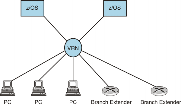
Your EE network might benefit from having an EE connection network. A connection network is a representation of a shared access transport facility (SATF) which enables nodes that identify their connectivity to the SATF by a common virtual routing node (VRN) to communicate without having individually defined connections to one another. Figure 1 shows VRN connectivity. A connection network is also referred to as a virtual routing node (VRN). Figure 1. VRN connectivity
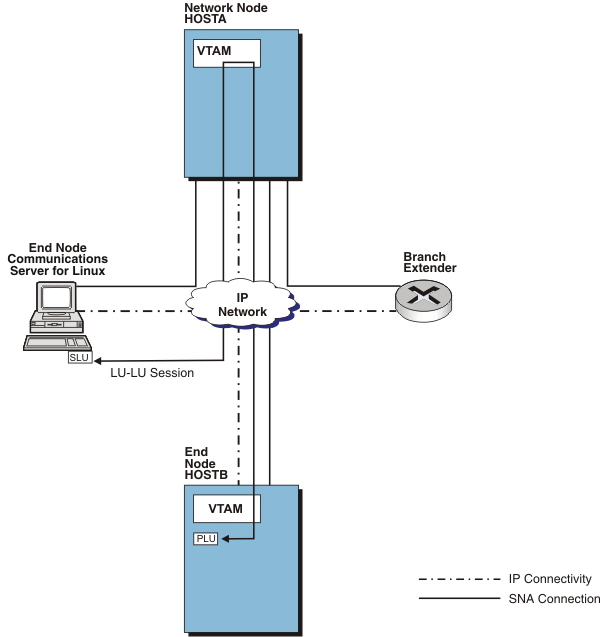
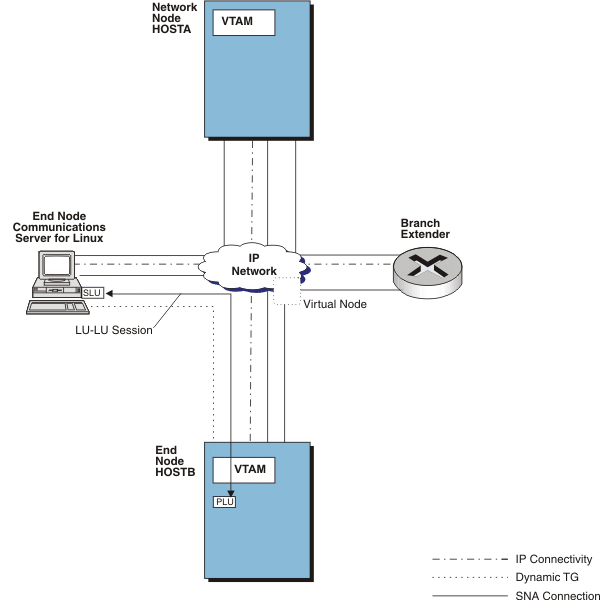
 Before you begin, you should understand the benefits and liabilities of an EE connection network. These are shown in the following figures. Figure 2, when an LU-LU session between resources on Communications Server for Linux and HOSTB is set up, the optimal route is directly through the network. However, if Communications Server for Linux and HOSTB are not directly defined to each other or are not connected to the same connection network, the indirect route is selected through HOSTA. Figure 2. VTAM® routing with an SATF
 Optimal route calculation is achieved in one of two ways:
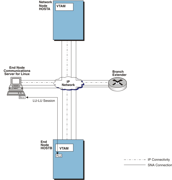
Defining connections between each pair of nodes enables optional route calculation, but requires (n*(n-1)) definitions (where n is the number of nodes). In Figure 3, for example, the LU-LU session no longer traverses HOSTA. Figure 3. VTAM routing meshed connections
 As the number of nodes in the network increases, the number of required connection definitions increases at an exponential rate. In a large network these definitions can be extensive. If you define a connection network to represent the shared access transport facility, system definition is reduced. With connection networks, end nodes need to define only a connection to a virtual node and to their network node server, which means only about (2*n) connection definitions. Figure 4 shows this concept. Figure 4. VTAM attachment to a connection network
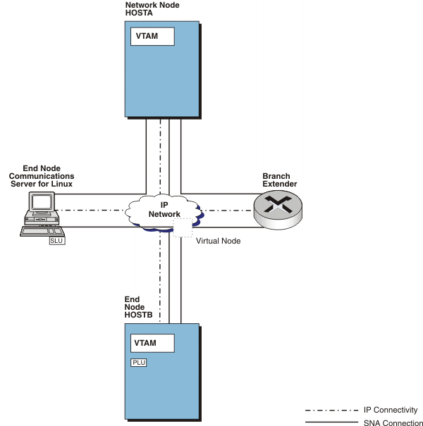 The virtual node is reported to the topology database and can be chosen as the intermediate node during route calculation. This is shown in Figure 5. Figure 5. VTAM optimal route calculations


|
 Copyright IBM Corporation 1990, 2014 Copyright IBM Corporation 1990, 2014 |