This appendix describes how to force the path of a route through
your network. You might want to force a route if you want certain
sessions to use a specific path rather than the default path.
If you use only the defaults, the nodes and links are considered
equal and the route with the fewest nodes and links will have the
least weight. The route with the least weight is selected as the route
for the session.
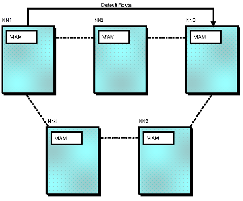
For example, if all the defaults are used in the network shown
in Figure 1 and an LU in NN1 requests a
session with an LU in NN3, the route chosen for the session will go
from NN1 through NN2 to NN3.
Figure 1. Sample network showing default
route
If you want to force a different route for a certain type of session,
you need to cause that route to have a lower weight than the original
default route. For example, you might want the session between the
LU in NN1 and the LU in NN3 in Figure 1 to
be routed through NN4 and NN5. By defining a new APPN Class of Service
and a transmission group (TG) profile, you can create a lower weight
for the route you choose than the weight of the default route.
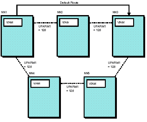
This example demonstrates using the UPARM1 operand to force a route to traverse NN1, NN4, NN5, and NN3. With
the defaults, the values for UPARM1 for the links in the network would
look like the example in Figure 2.
Figure 2. Sample network using default
for UPARM1
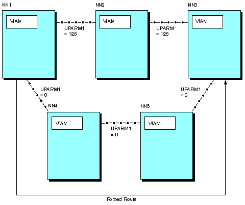
To create a lower weight for the chosen route, you can define a
TG profile with a UPARM1 value of 0 and specify that TG profile on
the PUs associated with the links between NN1 and NN4, NN4 and NN5,
and NN5 and NN3. The UPARM1 values in the network would then appear
as they do in Figure 3.
Figure 3. Sample network using TG
profile on some links
By defining UPARM1 on the TG profile as 0, the links that specify
that TG profile have a unique characteristic. You can define a new
Class of Service that will give preference to links with a lower UPARM1
value. The following steps describe how to define the TG profile and
define a Class of Service to take advantage of the UPARM1 value:
- Code a TG profile with UPARM1=0 as shown in the following example.
**********************************************************************
* TG Profile to change UPARM1 value                                  *
**********************************************************************
*
UPARMLOW TGP   UPARM1=0
- Specify this TG profile for the PUs associated with each line
in the preferred route.
-
Code a Class of Service (COS) that gives preference to links
using the TG profile.
Note: Use the APPNCOS statement to name
the new COS UPARMCOS.
- Copy the eighth LINEROW and NODEROW statements from the IBM-supplied
COS definition #CONNECT (found in the COSAPPN member of SYS1.VTAMLST).
- Make a second copy of the LINEROW statement.
- On the LINEROW statements, modify only the NUMBER, UPARM1, and
WEIGHT operands.
Modify the first LINEROW statement to specify
NUMBER=1, UPARM1=(0,99), and WEIGHT=30.
Modify the second
LINEROW statement to specify NUMBER=2, UPARM1=(100,255), and WEIGHT=240.
- File this new APPN COS definition in SYS1.VTAMLST under the new
member, COSSAMP. Use the VARY ACT command to activate this definition
by specifying ID=COSSAMP. (As an alternative, if VTAM® is not already active, you can specify
COSSAMP in your CONFIG list so that the definition will be activated
as part of VTAM initialization.)
- Define a mode table entry that specifies the new APPN COS definition
and add it to ISTINCLM or the mode tables associated with the LUs
(if the default mode table is not being used). The following code
is an example of the mode table entry.
         TITLE 'UPARMODE'
***********************************************************************
*                                                                     *
*        LOGMODE ENTRY FOR FORCED APPN ROUTE EXAMPLE -                *
*                                                                     *
***********************************************************************
UPARMODE MODEENT LOGMODE=UPARMODE,FMPROF=X'03',                        *
               TSPROF=X'03',PRIPROT=X'B1',SECPROT=X'A0',               *
               COMPROT=X'3040',                                        *
               APPNCOS=UPARMCOS
- Specify the new mode name, UPARMODE, when requesting the session.
- Because UPARMCOS is the APPN COS definition used by the route
selection process, the NN1 to NN2 to NN3 route has a weight of 240
+ 160 + 240 = 640 based on the values of the WEIGHT operand from the
UPARMCOS definition. Because the NN1 to NN4 to NN5 to NN3 route has
a weight of 30 + 160 + 30 + 160 + 30 = 410 based on the values of
the WEIGHT operand, it will be the chosen least-weight route.
Note: For this example, it is required that the new mode and Class
of Service tables be stored in the nodes that are the endpoints of
the session path; however, we strongly recommend that the Class of
Service and mode tables be consistent among all the nodes in the network.
The following example shows the new user-defined Class of Service.
**********************************************************************
* user-defined class-of-service definition                           *
**********************************************************************
UPARMCOS APPNCOS  PRIORITY=MEDIUM           transmission priority
         LINEROW  WEIGHT=30,                TG weight                  *
               NUMBER=1,                    line row number            *
               UPARM1=(0,99),               user defined parameter 1   *
               UPARM2=(0,255),              user defined parameter 2   *
               UPARM3=(0,255),              user defined parameter 3   *
               CAPACITY=(MINIMUM,MAXIMUM),  line speed                 *
               COSTTIME=(0,255),            cost per connect time      *
               COSTBYTE=(0,255),            cost per byte transmitted  *
               PDELAY=(MINIMUM,MAXIMUM),    propagation delay          *
               SECURITY=(UNSECURE,MAXIMUM)  security level for TG
         LINEROW  WEIGHT=240,               TG weight                  *
               NUMBER=2,                    line row number            *
               UPARM1=(100,255),            user defined parameter 1   *
               UPARM2=(0,255),              user defined parameter 2   *
               UPARM3=(0,255),              user defined parameter 3   *
               CAPACITY=(MINIMUM,MAXIMUM),  line speed                 *
               COSTTIME=(0,255),            cost per connect time      *
               COSTBYTE=(0,255),            cost per byte transmitted  *
               PDELAY=(MINIMUM,MAXIMUM),    propagation delay          *
               SECURITY=(UNSECURE,MAXIMUM)  security level for TG
         NODEROW  NUMBER=2,                 node row number            *
               WEIGHT=160,                  node weight                *
               CONGEST=(LOW,HIGH),          congestion                 *
               ROUTERES=(0,255)             route addition resistance
 z/OS Communications Server: SNA Network Implementation Guide


 Copyright IBM Corporation 1990, 2014