 z/OS Communications Server: SNA Network Implementation Guide
 z/OS Communications Server: SNA Network Implementation Guide
|
Previous topic |
Next topic |
Contents |
Contact z/OS |
Library |
PDF
Channel-attached NCP to a VTAM data host z/OS Communications Server: SNA Network Implementation Guide SC27-3672-01 |
|
|
You can define a channel attachment between a host and an NCP in a channel-attachment major node. This data host attachment eliminates the requirement for the host to have ownership (control) of network resources. It provides the ability for VTAM® to contact a channel-attached NCP without activating the NCP. By using this definition process, a VTAM data host is not required to establish an SSCP-PU session for data transfer to occur over the channel link to the communication controller. This method of attaching to the network prevents the data host from issuing requests on the SSCP-PU session that can affect the configuration of the local NCP major node or other nodes. The only definition required in the VTAM data host is a channel-attachment major node definition; no NCP load module, NCP resource resolution table (RRT), or copy of the NCP major node definition is needed. However, the NCP must be loaded and active if VTAM is to contact the NCP and not establish an SSCP-PU session. The GROUP definition statement defines channel-to-NCP links.
It also carries other operands that sift down to following definition
statements that do not explicitly override them. When you code LNCTL=NCP, VTAM does not have to have knowledge of the resources
attached to the NCP. Code one LINE definition statement for each channel-to-NCP
link and one PU definition statement for each LINE definition statement.
The LINE definition statement defines the following to VTAM:
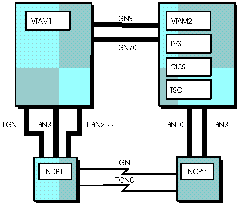
In Figure 1, the two channel connections between NCP2 and VTAM2 can be defined using a channel-attachment major node. In this case, VTAM1 is a host that owns all of the network resources attached to both NCP1 and NCP2. VTAM1 loads the NCPs and activates all of the resources. VTAM2 in this configuration is designated as the data host and thus does not own any network resources. The primary task of the data host (VTAM2) is to support application programs such as IMS™, CICS®, or TSO. All LU-LU sessions are therefore cross-domain sessions. Figure 1. Example NCP to VTAM data host connection
 The following example illustrates the definition statements used in the VTAM data host (VTAM2) to define one of the channel links between VTAM2 and NCP2. Another LINE definition statement and PU definition statement are required to define the other channel link (TG3) between VTAM2 and NCP2. The LINE definition statement defines the channel unit address for the channel link to the communication controller. The MAXBFRU operand defines the maximum number of I/O buffers that are used by the VTAM host to receive data from the NCP. This operand has the same meaning as the MAXBFRU operand that is specified on the HOST definition statement in the NCP and should contain the same value. The value of the ISTATUS operand on the LINE definition statement is INACTIVE. If ISTATUS=ACTIVE is specified, the activation process causes VTAM to issue the IST380I message with sense information (081C0010) that is unnecessary. By specifying INACTIVE as the status, the major node activation process completes, and the message is eliminated. The MAXDATA operand on the PU definition
statement also has the same meaning as the MAXDATA operand on the
PCCU definition statement. The operand specifies the maximum number
of bytes that VTAM can send
in a single-segment PIU. The TGN operand identifies the unique transmission
group number (10) that is associated with this channel-link connection.
In a multiple domain environment, parallel transmission groups
can be defined between VTAM and NCP similar to those in a single domain environment. This capability
allows you to add multiple channel attachments to an NCP subarea.
In Figure 1, the channel connections
between VTAM2 and NCP2 can be defined using channel-attachment major
node definitions. In this case, both TG10 and TG3 can be used to communicate
with NCP2 without activating NCP1. The transmission group number is
specified on the PU definition statement in the channel-attachment
major node. Each transmission group is limited to a single link TG.
Although you can have as many as 255 transmission groups, only 16
of these can be defined because of the following limitations:
Note: NCP2 can be activated
by the data host if ownership of the NCP2 resources is required as
a part of a backup and recovery scenario. This establishes the necessary
SSCP-PU session, but it requires the data host to maintain a copy
of the NCP major node in its VTAMLST and the NCP resource resolution
table (RRT). You could require a copy of the NCP load module at the
data host if the NCP needs to be reloaded and the communication controller
does not have a disk (the IBM® 3725, for example).


|
 Copyright IBM Corporation 1990, 2014 Copyright IBM Corporation 1990, 2014 |