 z/OS Communications Server: SNA Network Implementation Guide
 z/OS Communications Server: SNA Network Implementation Guide
|
Previous topic |
Next topic |
Contents |
Contact z/OS |
Library |
PDF
Channel-to-channel adapter connection z/OS Communications Server: SNA Network Implementation Guide SC27-3672-01 |
|
|
A channel-to-channel adapter connection between two host processors is defined using a channel-attachment major node. You define two channel-attachment major nodes for each connection. Each channel-attachment major node represents each VTAM's view of the connection. A GROUP definition statement defines the type of links that follow and also carries other operands that sift down to following definition statements that do not explicitly override them. Code one LINE definition statement for each channel-to-channel adapter. The LINE definition statement defines to VTAM® the characteristics of the line side of the adapter. Code one PU definition statement for each LINE definition statement. The definition statements in the following example define the channel link between the two VTAMs shown in Figure 1. On the GROUP definition statement, the missing interrupt handler (MIH) operand is coded with a value of YES so that the channel link becomes inoperative after the time period specified on the REPLYTO operand expires. (Otherwise, the channel link appears operative, but VTAM cannot use it.) The default for the MIH operand is NO. The LINE definition statement is used to specify the channel unit address (ADDRESS=51A) used in VTAM at one end of the channel link. You can use the following operands on the LINE definition:
Though the PU definition statement identifies the physical unit
type at the other end of the connection to be an NCP (PUTYPE=4), the
channel link actually connects to another VTAM, a physical unit type 5. The TGN operand
specifies a transmission group number for the channel-link transmission
group. Because parallel transmission groups between two subareas require
unique TG numbers, the TGN operand is used.
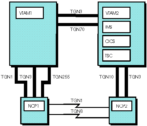
The capability of having parallel transmission groups allows you to add multiple channel attachments to an adjacent subarea host. With parallel transmission group support, VTAM permits the transmission group number to be specified on the PU definition statement of the channel-attachment major node and on the PATH definition statement. For information about how this affects network routing, see Parallel sessions using parallel transmission groups. Although you can have as many as 255 transmission groups, only 16 of these can be defined because the maximum number of explicit routes that can be defined between two adjacent VTAMs is 16. Each transmission group is single-link capable only. Figure 1 illustrates a possible configuration of parallel transmission groups. Figure 1. Parallel transmission groups
in multiple domain environment with NCP
 Two channel-to-channel connections are configured in Figure 1. A LINE and a PU definition statement are required for each of these channel connections between the two VTAMs. The TGN operand for one of the channel connections specifies a transmission group number of 3, as shown in the previous example. The LINE definition statement that defines the other channel-link connection must have a TGN operand that specifies a transmission group number of 70. Parallel transmission group support limits each transmission group to a single channel-to-channel link. The two channel-link connections (TG3 and TG70) between the VTAMs cannot be defined as a single logical transmission group composed of the two channel links. 


|
 Copyright IBM Corporation 1990, 2014 Copyright IBM Corporation 1990, 2014 |