When you split message flow processing between different
integration servers, you must configure a data router and a connectivity
agent. The integration servers can be running on different integration
nodes.
About this task
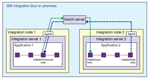
When you split processing between different integration servers, your flows communicate by using
a Switch server and connectivity agents. The Switch server is a special kind of integration server
that routes data. The connectivity agents contain the certificates that your flows require to
communicate securely with the Switch server. A connectivity agent must be running in each
integration server where you have deployed message flows. The integration servers can be in the same
integration node or in different integration nodes, as shown in the following example.
If you are splitting processing between
IBM Integration Bus and
IBM App Connect on IBM Cloud, the Switch
server is created and managed for you in the cloud. If your callable flows are all deployed on
premises, you must create and configure the Switch server. You must run a command that creates some
configuration files. You use one of the configuration files to create the Switch server, and the
other file to configure connectivity agents for each integration server where you have deployed
callable flows.
This scenario
is supported on Windows and Linux® only.
Procedure
To prepare the environment to split processing between
integration servers, complete the following steps.
- Start an IBM Integration Bus command
environment.
- Run the iibcreateswitchcfg command
to create the required configuration files.
You need
to run the command in a directory for which you have permission to
write. Alternatively, you can specify an output directory. For example,
the following command creates the configuration files and saves them
in the
temp directory.

On
Windows:
iibcreateswitchcfg /output c:\temp

On
Linux:
iibcreateswitchcfg -output /temp
If this command is successful, you see the following responses:
Generated self signed certificate file 'c:\temp\adminClient.p12'
Generated switch configuration file 'c:\temp\switch.json'
Generated agentx configuration file 'c:\temp\agentx.json'
This
command creates two JSON configuration files, and a certificate, which
is reserved for future use. One file (
switch.json)
is used to create the Switch server. The other file (
agentx.json)
is used by the
mqsichangeproperties command
to configure secure connectivity for the integration servers where
your flows are deployed.
- Run the iibswitch command
to create the Switch server by using the configuration file (switch.json)
that you created in step 2.

For
example, on
Windows:
iibswitch create switch /config c:\temp\switch.json

On
Linux:
iibswitch create switch -c /temp/switch.json
If the command is successful, you see the following response:
iibswitch created and started
The Switch server is created in a special integration
node called IIBSWITCH_NODE.
- Optional: To test that the Switch server is
created and running, run the command
mqsilist IIBSWITCH_NODE.
If the Switch server is running, you see the following
response:
BIP1286I: Integration server 'IIBSWITCH_SERVER' on integration node 'IIBSWITCH_NODE' is running.
- Run the mqsichangeproperties command
for each integration server where you have deployed message flows.
For example, the following command uses the integration server
configuration file (
agentx.json) that you created
in step 2.
mqsichangeproperties integrationNodeName -e integrationServerName -o ComIbmIIBSwitchManager -n agentXConfigFile -p filepath\agentx.json
This command ensures that the integration servers have
the correct certificates to communicate securely with the Switch server.
- Restart the integration nodes that contain the affected
integration servers.
- Verify that your nodes have connected to the
switch, by running the mqsireportproperties command
as described in Determine the status of the switch server for callable flows.
Results
A message flow that is deployed to one configured integration
server can now communicate securely with a message flow on the other
configured integration server. For more information about developing
these message flows, see Developing synchronously callable message flows.
 If you are splitting processing between IBM Integration Bus and IBM App Connect on IBM Cloud, the Switch
server is created and managed for you in the cloud. If your callable flows are all deployed on
premises, you must create and configure the Switch server. You must run a command that creates some
configuration files. You use one of the configuration files to create the Switch server, and the
other file to configure connectivity agents for each integration server where you have deployed
callable flows.
 On
On  On
On