Callable message flows
A message flow can call another flow directly. You can deploy both flows to IBM® Integration Bus or IBM App Connect on IBM Cloud. You can also deploy one flow to IBM Integration Bus and one flow to IBM App Connect on IBM Cloud.
A message flow can complete many different actions. If any of those actions are labor-intensive, you can split them from the main flow and complete them somewhere else. Callable flows also facilitate reuse because they can be called by multiple message flows. You can split your flows between different applications in the same integration server, or between different integration servers, which can also be in different integration nodes. Your callable flows must be in applications. You cannot deploy callable flows in libraries or integration projects.
Some parts of a message flow might logically belong in a specific location. For example, if your flow queries an on-premises database, performance is better if that part of the flow remains on premises. But if part of your flow queries a website multiple times, performance might be improved by running that part of the flow in the cloud. You can call the cloud-based flow from your on-premises flow, and the flow in the cloud does not use any of your on-premises resources.
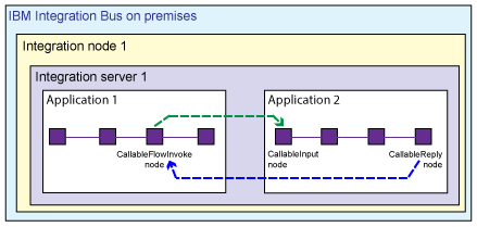
If your callable flows are both deployed to IBM App Connect on IBM Cloud, they can communicate with each other as soon as you deploy them. You do not need to set up communication between them. You also do not need to set up communication if both flows are deployed to the same integration server on IBM Integration Bus.
If you are splitting processing between different integration servers, or between IBM Integration Bus and IBM App Connect on IBM Cloud, your flows communicate by using a Switch server and connectivity agents. The Switch server is a special type of integration server that routes data. You cannot deploy anything to the Switch server. The connectivity agents contain the certificates that your flows require to communicate securely with the Switch server. The connectivity agents must be running in the integration servers where you have deployed your on-premises message flows. To start the agents, and to ensure that they are using the correct certificates to communicate securely with your cloud-based flow, you run the mqsichangeproperties command for each integration server.
You can split processing synchronously between message flows by using the CallableFlowInvoke node in the calling flow, and CallableInput and CallableReply nodes in the callable flow. Alternatively, you can split processing asynchronously between message flows, by using the CallableFlowAsyncInvoke node in the calling flow, CallableInput and CallableReply nodes in the callable flow, and the CallableFlowAsyncResponse node in the response flow. You can also choose to share data between the flows that contain these asynchronous nodes (the calling flow and the response flow) by storing and retrieving data in the UserContext folder in the Environment. For more information about sharing data between flows, see Sharing data between a calling flow and a response flow.
You can split flows into multiple callable flows. However, for simplicity, the following scenarios assume that you are using two flows only: a calling flow and a callable flow.
Scenarios
Splitting flows synchronously between applications on the same integration server
Splitting flows synchronously between applications on different integration servers
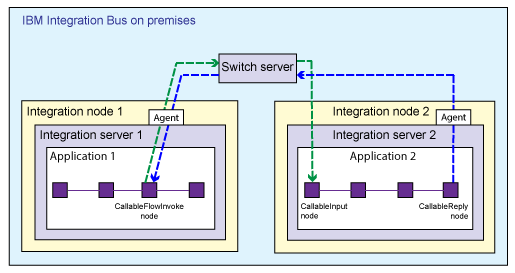
If your flows are split between different integration servers in IBM Integration Bus, you must run a command that creates some configuration files. You use one of the configuration files to create the Switch server, and the other file to configure connectivity agents for each integration server. This scenario is supported on Windows and Linux® only.
Splitting flows synchronously between IBM Integration Bus and IBM App Connect on IBM Cloud
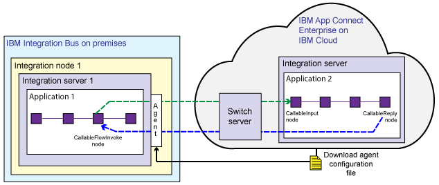
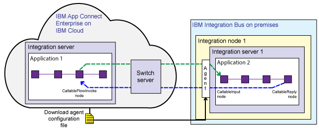
If your flows are split between IBM Integration Bus and IBM App Connect on IBM Cloud, the Switch server is managed by IBM App Connect on IBM Cloud. You download a file from the cloud that configures an on-premises connectivity agent. This scenario is supported on Windows and Linux only.
Splitting flows asynchronously in IBM Integration Bus, or between IBM Integration Bus and IBM App Connect on IBM Cloud
A message flow contains a CallableFlowAsyncInvoke node, which calls a second (callable) message flow containing a CallableInput node and a CallableReply node. A third (response) flow contains a CallableFlowAsyncResponse node.
When a message is passed into the calling message flow, the CallableFlowAsyncInvoke node sends the contents of the message body and environment folders to the CallableInput node of the callable flow, and then completes immediately. When the callable flow completes processing, the CallableReply node sends the message body and environment folder data to the CallableFlowAsyncResponse node in the response flow.
If your flows are split between different integration servers, you must create a Switch server (which routes data) and connectivity agents to allow the flows to communicate securely. For more information, see Preparing the environment for callable flows.
Flow configuration
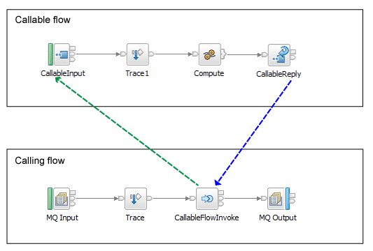
In this example, the CallableFlowInvoke node parses the incoming message in full so that it is in a suitable format to send to the CallableInput node. Therefore, you should validate the message before it reaches the CallableFlowInvoke node. If the message fails validation at this point, it can be rolled back.
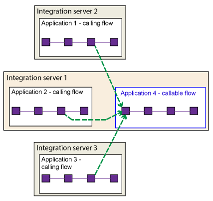
You can add multiple CallableFlowInvoke or CallableFlowAsyncInvoke nodes to a message flow. You can also include CallableFlowInvoke or CallableFlowAsyncInvoke nodes in your callable flows. Application and endpoint name pairs must be unique on a single integration server. You can have multiple callable flows that have the same application and endpoint names, but they must be in different integration servers. In this case, the Switch server acts as a load balancer.
Deployment
After you develop your message flows, you package the containing applications into BAR files and deploy them to the appropriate locations. If the flow accesses on-premises resources, deploy its BAR file on premises. If the flow will run in the cloud, upload its BAR file to IBM App Connect on IBM Cloud.
When the calling flow receives an input message, the CallableFlowInvoke (or CallableFlowAsyncInvoke) node uses the application name and the Endpoint Name on the CallableInput node to identify and start the callable flow.
The Callable Flows tutorial in the Tutorials Gallery demonstrates how to use the callable flow nodes to split processing between flows. In the IBM Integration Toolkit, click , then select Callable Flows.
For detailed information about how to configure callable message flows, see Splitting the processing of message flows.