Before you begin
- Connect the blueprint design server to a cloud system. See Connecting to clouds through OpenStack Heat.
- Make sure that your user account is authenticated to a cloud system. See Setting up authentication to OpenStack Heat clouds for the blueprint designer.
- Connect the blueprint design server to the server. See Connecting the blueprint design server to the server.
- Log in to the blueprint designer.
- At the top of the page, select the cloud project and region to use.
About this task
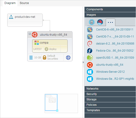
To edit a blueprint in the graphical editor, open the blueprint by clicking Blueprints, and then from the Files list, select a blueprint. The Diagram tab shows the blueprint in a graphical editor.

To edit the source code of a blueprint, click the Source tab. For more information, see Editing blueprint source code.
- If you import a blueprint into another blueprint, the Imported drawer shows the components from the imported blueprint that must be placed in the active blueprint.
- The Components drawer shows components and tags from the IBM® UrbanCode™ Deploy server
and, if you integrated with Chef, Chef roles. You can drag these components to a virtual image. If
you drag a component tag to a virtual image, all the components on the IBM UrbanCode Deploy server
that contain that tag are added to the blueprint.
This drawer also includes a resource that is named Referenced Component. This resource represents a generic component. You can use the referenced component to represent a component that you specify later.
- The Images drawer shows virtual images that are available on the current
cloud system. You can drag these images to the blueprint.
This drawer also includes a resource that is named Referenced Image. This resource represents a generic virtual image. You can use the referenced image to represent a virtual image that you specify later. By using referenced images in this way, you can create one blueprint that you can provision on multiple clouds; see Editing configuration files.
Restriction: To be used with the blueprint designer, the virtual images must meet the requirements in Configuring images for use with the blueprint designer. - The Networks drawer shows networks that are available on the cloud. The New Internal Network resource represents a new network. The Referenced Network resource represents a network for which you provide information later.
- The Security drawer shows security configurations that you can apply to virtual images. The New Security Group resource represents a new security configuration. The Referenced Security Group resource represents a security configuration for which you provide information later.
- The Storage drawer shows cloud storage volumes. To add a storage volume, drag a volume to a virtual image. The New Storage Volume resource represents a new storage volume. The Referenced Storage Volume Attachment resource represents a storage volume for which you provide information later.
- The Policies drawer includes resources such as load balancers and autoscaling groups.
- The Templates drawer includes all the Heat resources that are available
on your cloud, including resources that are not supported by the blueprint diagram editor. To add
any resource, drag it onto the blueprint. You can add resources only by using this method in the
graphical editor.
When you add a resource to a blueprint, you must update its properties in the source editor. Each property is formatted to accept the correct inputs, and all required properties in the resource are labeled. The names of resources that you add from the Templates drawer are appended with -dsp in the source editor. If you add the -dsp suffix to the names of existing resources, they are displayed in the graphical editor.
To search the palette contents, click Add
![]() , and then in the Add Element window enter your search term in the
filter field.
, and then in the Add Element window enter your search term in the
filter field.
You can drag resources to different places in the diagram. To connect an image to a network, drag a connection from the image to the network or vice versa. When you are finished editing, click Save.
When you click a resource to select it, its properties are displayed in the Properties drawer, to the left of the editor. From this drawer, you can change property values or externalize them to properties as described in Externalizing properties in blueprints.
If the blueprint contains an error, warning, or unfinished TODO item, you cannot
provision from it. If at least one of these items is present in a blueprint, an icon that represents
the most serious type of item is displayed to the right of Toggle
Comment![]() . For example, if the blueprint contains at least one error, the error icon
. For example, if the blueprint contains at least one error, the error icon ![]() is displayed. Hover over the icon to display a list of all items that you must correct or
complete before you provision the blueprint.
is displayed. Hover over the icon to display a list of all items that you must correct or
complete before you provision the blueprint.
For information about the common types of resources that appear in blueprints, see Overview of blueprints.
resource_tree:
  type: IBM::UrbanCode::ResourceTree
  properties:
     urbancode_deploy_url: { get_param: ucd_server_url }
     username: { get_param: ucd_user }
     password: { get_param: ucd_password }
     team_mappings:
     application: MyApplication
     base_resource_group: MyResources