|
You can either statically or dynamically define
a channel-attached NCP.
ProcedureTo define a channel-attached NCP, take the following
steps: - Code a PCCU definition statement.
- The CUADDR operand on the PCCU definition statement specifies
the channel address of the channel adapter on the NCP that is used
to perform the load operation. The operator can also specify the channel
unit address on the VARY ACT operator command. VTAM® identifies the channel link and link station
by using the channel unit address.
- The LOADSTA and DUMPSTA operands on the PCCU definition statement
can also be used to identify to VTAM the channel-link station to be used to load and dump the
NCP.
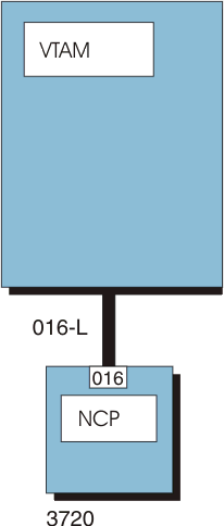
Following is a sample PCCU definition statement for the
channel-attached NCP in Figure 1: PCCU116 PCCU CUADDR=016, 3720 IPL ADDRESS
DUMPDS=NCPDUMP, NCP DUMP DATA SET DDNAME
MDUMPDS=MOSSDUMP, MOSS DUMP DATA SET DDNAME
CDUMPDS=CSPDUMP, CSP DUMP DATA SET DDNAME
VFYLM=YES, NOTIFY OPERATOR IF WRONG LOAD MODULE
VFYC=YES, VERIFY LOAD MODULE AND RRT MATCH
⋮
SUBAREA=116 OWNING SSCP SUBAREA
In Figure 1, VTAM uses the CUADDR operand from the PCCU definition
statement (016) to define the channel link (016-L) and channel link
station (016-S). VTAM will
load the 3720 using channel link 016-L.
Figure 1. Channel-attached 3720 Communication Controller
VTAM chooses default
link stations that are adjacent to the NCP and ready for the dump
operation. Preference is given to channel-link stations.
If
a channel-attachment major node and its link and link station minor
nodes are active when this NCP is activated, use the channel-link
station name that is defined by the PU definition statement in the
channel-attachment major node for the DUMPSTA, LOADSTA, and RNAME
operands of PCCU.
- Code a BUILD definition statement.
Following
is an example of the operands on the BUILD definition statement: BUILD BUILD BFRS=240, SIZE OF NCP BUFFERS
⋮
CA=(TYPE5,TYPE5), CA TYPES
DELAY=(.2,.2), CA ATTENTION DELAYS
NCPCA=(ACTIVE,ACTIVE), CA STATUS
TIMEOUT=(30,30) CA ANS — HOST FAILURE
One of the channel links is used to load the NCP.
- You can also define channel links using the GROUP, LINE, and PU definition
statements of the NCP for a 3745 and optionally for a 3725 and 3720. The information about the channel-link characteristics can be
coded as operands on these definition statements, similar to those
used on the BUILD definition statement (CA, NCPCA, DELAY, and TIMEOUT).
Code a LINE and a PU definition statement for each channel adapter.
The names used to identify the channel link and link station to VTAM are the names specified on
the LINE and PU definition statements, respectively.
Following
is an example of how channel links can be
defined using the GROUP, LINE, and PU definition statements of the
NCP: N111CA GROUP LNCTL=CA CHANNEL ADAPTER DEFINITIONS
L5CA05 LINE ADDRESS=00, CHANNEL ADAPTER 5 RELATIVE ADDRESS
CASDL=125, CHAN ADAPTER SLOWDOWN DELAY
NPACOLL=YES, NPA COLLECTION
⋮
CA=TYPE6, CHANNEL ADAPTER TYPE
DELAY=.1, CHANNEL ATTENTION DELAY
NCPCA=ACTIVE, CHANNEL ADAPTER STATUS
TIMEOUT=180, CHANNEL ADAPTER ANS - HOST FAILURE
TRANSFR=20, MAXIMUM DATA TRANSFER SIZE
ISTATUS=ACTIVE VTAM STATUS
*
P5CA05 PU PUTYPE=5, VTAM HOST CONNECTION — PUTYPE5
TGN=1 channel link TRANSMISSION GROUP NUMBER
What to do nextSee Dynamic configuration of channel-attached devices for
information about implementing dynamic definitions. See Defining type 2.1 peripheral nodes if you want to define your channel-attached
NCP as a type 2.1 device and define the logical unit either dynamically
or statically. 


|
 z/OS Communications Server: SNA Network Implementation Guide
 Copyright IBM Corporation 1990, 2014