 z/OS Communications Server: SNA Network Implementation Guide
 z/OS Communications Server: SNA Network Implementation Guide
|
Previous topic |
Next topic |
Contents |
Contact z/OS |
Library |
PDF
Logical paths z/OS Communications Server: SNA Network Implementation Guide SC27-3672-01 |
|
|
The logical path between two subarea nodes is a virtual route.
The eight virtual routes and three levels of transmission priority
provide for the possibility of 24 virtual route and transmission priority
pairs between two subarea nodes. In other words, each subarea pair
can have virtual routes numbered 0 through 7 between them, and each
virtual route can have up to three different transmission priorities.
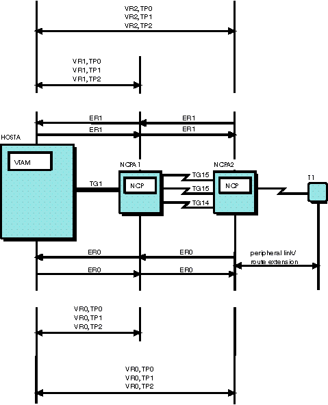
As shown in Figure 1, a virtual route must be defined for each explicit route pair. For example, between HOSTA and NCPA1, VR0 is associated with ER0 and reverse ER0, and VR1 is associated with ER1 and reverse ER1. Between HOSTA and NCPA2, VR0 is associated with ER0 and reverse ER0, and VR2 is associated with ER1 and reverse ER1. Data flows at a designated transmission priority over a virtual route. In this arrangement, data can flow over any of the virtual routes at transmission priority 0,1, or 2. Figure 1. Virtual route and explicit route associations
and transmission priority


|
 Copyright IBM Corporation 1990, 2014 Copyright IBM Corporation 1990, 2014 |