This topic explains how to implement a VTAM® network and includes the following topics:
- Using start options and configuration lists
- Identifying resources to VTAM
- Verifying a VTAM network
Implementing a VTAM network
involves the following tasks:
- Use of start options and an optional configuration list
- Identification of particular resources in the network to VTAM
- Identification of any paths required for network routing
- Establishment of sessions
- Operation of VTAM itself
You will also need to understand the VTAM start procedure and the associated data sets. For information
about this process, see z/OS Communications Server: New Function Summary.
This topic gives descriptions of VTAM network requirements and an example of implementing a VTAM network and includes the following
subtopics:
- Start options
- Start options control the conditions under which VTAM runs. No matter what network configuration
you are implementing, you need to code some start options. Start options
are coded in files named ATCSTRxx, where xx specifies the identifier
of a particular start option file.
- Configuration list
- A configuration list lets you specify which resources are activated
automatically when you start VTAM. You are not required to define a configuration list, but it makes
the VTAM operator's job easier
because VTAM activates the
resources in the configuration list automatically. Configuration lists
are coded in files named ATCCONxx, where xx specifies the identifier
of a particular configuration list.
- Application programs
- Each host application program you are running must be defined to VTAM as an application program
minor node within an application program major node. A major node,
such as an application program major node, is a set of minor nodes
(in this case, the application programs) that can be activated and
deactivated as a group. For more information about application programs,
see Application programs.
Note: An application
program may become a shadow resource if a CDRSC with the
same name already exists when the major node containing the application
program's definition is activated. For more information about shadow
resources, see
Shadow resources.
- Subarea nodes
- If you have one or more NCPs in your network, define them in NCP
major nodes and channel-attachment major nodes.
If there are other
VTAMs in your network, define connections to them in NCP major nodes,
channel-attachment major nodes, or external communication adapter
(XCA) major nodes. If your VTAM is to have SSCP-SSCP sessions with other VTAMs, also create a cross-domain
resource manager major node and minor nodes for your VTAM and adjacent VTAMs with which your VTAM is to have such sessions.
You need to define paths for data flow between VTAM and any owned NCPs, and for data flow to
and from other VTAMs and NCPs in your network over subarea connections.
Paths are defined in PATH definition statements.
- APPN nodes
- If VTAM is going to use
APPN functions, specify the NODETYPE start option.
- Peripheral nodes
- Other physical devices in your network must also be defined to VTAM, whether they are directly
attached to the host or to an NCP. Peripheral nodes are dynamically
defined or manually defined in channel-attachment, external communication
adapter, local non-SNA, local SNA, LU group, model, packet, and switched
major nodes. Logical units in or attached to peripheral nodes are
defined with LU statements along with the peripheral nodes in the
major node definitions, or if they are independent LUs, they can be
defined in cross-domain resource major nodes. The major node you choose
depends on the characteristics of the device you are defining.
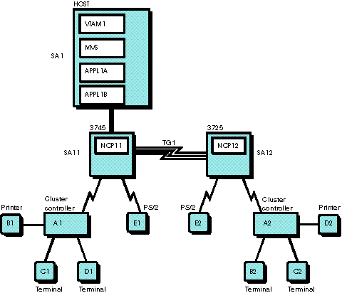
Figure 1 is a sample VTAM subarea network. The host is running MVS™, VTAM, and two VTAM application
programs. NCP11 is a channel-attached 3745 controller, and NCP12 is
a link-attached 3725 controller. Peripheral nodes are connected using
leased lines.
You need to code at least the following
resources to define the network in
Figure 1:
 z/OS Communications Server: SNA Network Implementation Guide


 Copyright IBM Corporation 1990, 2014