z/OS Communications Server: SNA Network Implementation Guide
Previous topic | Next topic | Contents | Contact z/OS | Library | PDF


Using a connection network

z/OS Communications Server: SNA Network Implementation Guide
SC27-3672-01

A connection network is a representation of a shared access transport facility (SATF), such as a local area network (LAN). This arrangement enables nodes identifying their connectivity to the SATF by a common virtual routing node to communicate without having individually defined connections to one another. This is illustrated in the following figures.

In Figure 1, when an LU-LU session between resources at AS400A and HOSTB is set up, the optimal route is directly through the token ring between the two nodes. However, if AS400A and HOSTB are not directly defined to each other or are not connected to the same connection network, the indirect route is selected through HOSTA.

Figure 1. VTAM attachment to a LAN—No meshed connection definitions
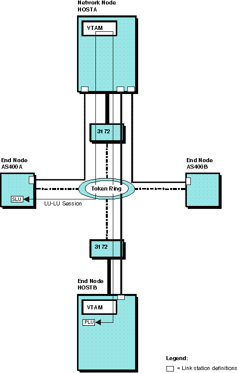
Example of a VTAM attachment to a LAN—No meshed connection definitions.
Optimal route calculation is achieved in one of two ways:
  • Meshed connection definitions
  • Connection network definition

A definition for the connection between each pair of nodes, (n*(n-1)) definitions where n equals the number of nodes, enables optimal route calculation between all nodes on the SATF. In Figure 2, for example, the pictured LU-LU session no longer traverses HOSTA.

Figure 2. VTAM attachment to a LAN—Meshed connection definitions provide optimal route calculation
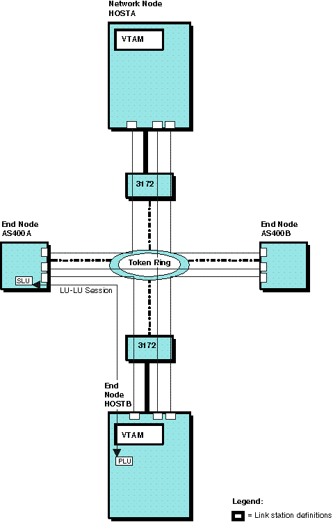
Example of a VTAM attachment to a LAN—Meshed connection definitions provide optimal route calculation.

In a large network, however, this system definition is extensive. System definition is greatly reduced by defining a connection network to represent the shared access transport facility (here, the token ring). In a connection network, end nodes need to only define a connection to a virtual node, as shown in Figure 3.

Figure 3. VTAM attachment to a connection network reduces required connection definitions (token ring)
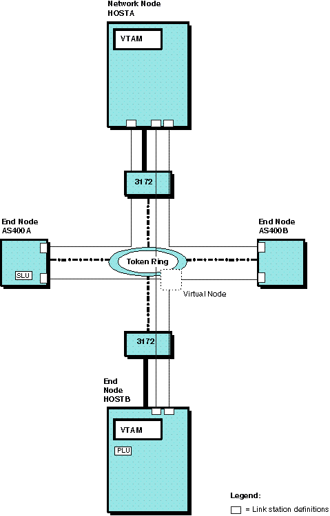
Example of a VTAM attachment to a connection network that reduces required connection definitions (token ring).

The virtual node is reported to the topology database and can be chosen as the intermediate node during route calculation. As shown in Figure 4, BINDs can then be routed directly to the destination node over a dynamically created TG. Thus, the definition of a connection network to represent the token ring reduces required system definition and enables optimal route calculation.

Figure 4. VTAM attachment to a connection network also enables optimal route calculation (token ring)
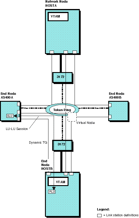
Example of a VTAM attachment to a connection network that enables optimal route calculation (token ring).
To define a connection to a connection network, include the following in the NCP major node, the XCA major node, or the LAN major node:
  • In the NCP major node [NTRI (NCP token ring interconnect) physical lines]:
    • Code the VNNAME and VNGROUP operands on the LINE definition statement. The VNNAME operand specifies the CP name of the virtual node. The VNGROUP operand specifies the name of the logical group containing dial-out links through the connection network named on the VNNAME operand.
      Note: DYNPU=YES is the default when VNNAME and VNGROUP are coded. For more information about DYNPU, see Defining resources dynamically.
    • Optional operands on the LINE definition statement include the TGP operand to indicate a TG profile containing TG characteristics, or operands for individual TG characteristics.
  • In the XCA major node (IBM® 3172 Nways Interconnect Controller lines):
    • Code the VNNAME and VNGROUP operands on the PORT definition statement. The VNGROUP operand specifies the GROUP in this major node containing the lines for the virtual node named on the VNNAME operand.
      Note: DYNPU=YES is the default when VNNAME and VNGROUP are coded. DIAL=YES is required on the GROUP named on the VNGROUP operand.
    • Optional operands on the PORT definition statement include the TGP operand to indicate a TG profile containing TG characteristics, or operands for individual TG characteristics.
  • In the LAN major node:
    • Code the VNNAME and VNGROUP operands on the PORT definition statement. The VNGROUP operand specifies the GROUP in this major node containing the lines for the virtual node named on the VNNAME operand.
      Note: DYNPU=YES is the default when VNNAME and VNGROUP are coded. DIAL=YES is required on the GROUP named on the VNGROUP operand.
    • Optional operands on the PORT definition statement include the TGP operand to indicate a TG profile containing TG characteristics, or operands for individual TG characteristics.
Notes:
  1. NCP Version 7 Release 1 is required for NCP/Token-Ring interconnection (NTRI) support of connection network.
  2. If CP-CP sessions are required between two nodes on the shared access transport facility, the dialing-out node must define the PU for any node it is to call; routes traversing a virtual node cannot be used for CP-CP sessions.
  3. The dial-out node can use only a dynamically defined PU for connectivity. The dial-in node attempts to use a predefined PU, if one exists. Otherwise, it uses a dynamically defined PU.
  4. An ADJCP definition statement with the VN=YES operand can optionally be placed into the adjacent control point major node. The VN=YES operand indicates that this adjacent CP is a virtual node. The VN operand cannot be specified when the NN operand or the DYNLU=YES operand is also specified.
  5. Both VTAM® end nodes and network nodes can define a connection to a virtual node.
  6. A connection network can be a node in an HPR route.
  7. Available lines must exist for the call through the connection network both within the dial-out node and the dial-in node. For the dial-out node, available lines must exist in the group specified by the VNGROUP keyword. The dial will fail if no connectable line is found. With multiple virtual node definitions between two real nodes, if the VNGROUP keywords specify different groups, because either route through the virtual node may be selected (depending upon the topological weight), it causes the connection network function to attempt to locate a connectable line in a group without one. For the dial-in node, a connectable line must be available for the call through the connection network. If all lines are busy with other calls, the call through the connection network will fail.
  8. By default, dynamic connection network PUs take a name in the format CNVxxxxx, where xxxxx is a unique value that is generated and concatenated to the default CNV prefix to create the eight-character PU name. To specify a different prefix (two characters), use the DYNVNPFX start option.
  9. A model PU definition can be created to customize the characteristics of dynamically created PUs. Use the DYNTYPE=VN operand for the model PU definition in the model major node.

Go to the previous page Go to the next page


Copyright IBM Corporation 1990, 2014