Learn about the specifications and operating system requirements for the 5773 adapter.
The 4 Gigabit PCI Express Single Port Fibre Channel Adapter is a 64-bit, short form factor x4, PCIe adapter with an LC-type external fiber connector that provides single initiator capability over an optical fiber link or loop. The adapter automatically negotiates the highest data rate between the adapter and an attaching device at 1 Gbps, 2 Gbps, or 4 Gbps of which the device or switch is capable. Distances between the adapter and an attaching device or switch can reach up to 500 meters running at 1 Gbps data rate, up to 300 meters running at 2 Gbps data rate, and up to 150 meters running at 4 Gbps data rate. When used with IBM® Fibre Channel storage switches supporting long-wave optics, the adapter can reach distances of up to 10 kilometers running at either 1 Gbps, 2 Gbps, or 4 Gbps data rates.
The adapter can be used to attach devices either directly, or by means of Fibre Channel switches. If you are attaching a device or switch with a SC type fiber connector, you must use an LC-SC 50 micron fiber converter cable (#2456) or a LC-SC 62.5 micron fiber converter cable (#2459).
The adapter has the following features:

50/125 micron fiber (500 MHz*km bandwidth cable)
62.5/125 micron fiber (200 MHz*km bandwidth cable)
The adapter is supported under the following operating systems:
 .
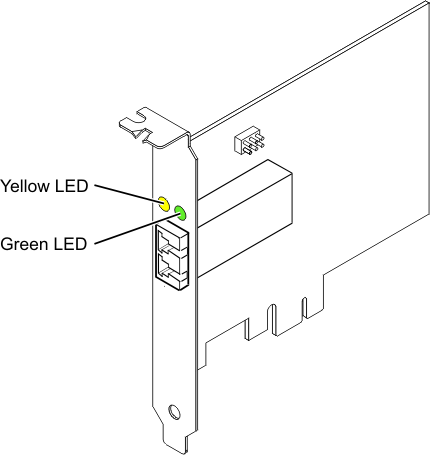
.Green and yellow LEDs can be seen through openings in the adapter's mounting bracket. Green indicates firmware operation and yellow signifies port activity. Table 1 summarizes normal LED states. There is a 1 Hz pause when the LED is off between each group of fast blinks (1, 2 or 3). Observe the LED sequence for several seconds to ensure that you correctly identify the state.
| Green LED | Yellow LED | State |
|---|---|---|
| On | 1 fast blink | 1 Gbps link rate - normal, link active |
| On | 2 fast blinks | 2 Gbps link rate - normal, link active |
| On | 3 fast blinks | 4 Gbps link rate - normal, link active |
Power-On Self Test (POST) conditions and results are summarized in Table 2. These states can be used to identify abnormal states or problems.
| Green LED | Yellow LED | State |
|---|---|---|
| Off | Off | Wake-up failure (dead board) |
| Off | On | POST failure (dead board) |
| Off | Slow blink | Wake-up failure monitor |
| Off | Fast blink | Failure in post |
| Off | Flashing | Post processing in progress |
| On | Off | Failure while functioning |
| On | On | Failure while functioning |
| Slow blink | Off | Normal, link down |
| Slow blink | On | Not defined |
| Slow blink | Slow blink | Offline for download |
| Slow blink | Fast blink | Restricted offline mode, waiting for restart |
| Slow blink | Flashing | Restricted offline mode, test active |
| Fast blink | Off | Debug monitor in restricted mode |
| Fast blink | On | Not defined |
| Fast blink | Slow blink | Debug monitor in test fixture mode |
| Fast blink | Fast blink | Debug monitor in remote debug mode |
| Fast blink | Flashing | Not defined |
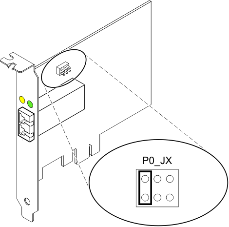
The default setting for the device ID jumper labeled P0_JX is to set the jumper on pins 1 and 2 as shown in Figure 2. Do not change the jumper settings for a standard installation.

Fibre Channel host bus adapters (HBAs) connected to a FAStT or DS4000® storage subsystem have a child device called a disk array router (dar). You must unconfigure the disk array router before you can hot swap an HBA that is connected to a FAStT or DS4000 storage subsystem. For instructions, refer to Replacing hot swap HBAs in the IBM System Storage® DS4000 Storage Manager Version 9, Installation and Support Guide for AIX®, HP-UX, Solaris, and Linux on POWER®, order number GC26-7848.