Troubleshooting
Problem
This document shows how to cable the Ethernet connection from the HMC to the managed Server.
Resolving The Problem
This document shows how to cable the Ethernet connection from the HMC to the managed Server FSP, or eBMC.
Note: Determine the physical location of the HMC in relation to the servers it manages. If the HMC is more than 25 feet from its managed system, you must provide web browser access to the HMC from the managed system's location so that service personnel can access the HMC. If this distance specification is not adhered to, the hardware warranty of the managed system can be voided.
This document assumes the typical configuration where the HMC eth0 port is configured as a DHCP server on a private network and cabled to the HMC1 port on the managed server. The location of the HMC eth0 port varies depending not only on the HMC model but also the number and type of adapters as well as the version of HMC. However, the information contained in this document shows the typical location of eth0 it is highly recommended that you confirm the location by testing for link status changes.
Locating eth0 using link status
This technique assumes you have a good CAT 5 or CAT 6 Ethernet cable connected to another active Ethernet port (the FSP HMCx port or a switch port). To use link status to locate eth0, do the following:
| 1. | Check link status. V7.3.3 and later: Click HMC Management, Test Network Connectivity, then click the Ethernet Settings tab. Note the Link detected setting for each adapter (yes/no). All Versions: Open a restricted shell terminal as hscroot. Enter the command tail -F /var/log/messages |
| 2. | Remove/Insert the cable to the typical eth0 location to change the link status. Wait one minute for link status to change. |
| 3. | Check link status again. V7.3.3 and later: Click the refresh button. All Versions: Check the log for an entry with "ethx: .... Link is up"(active) or ethx ... Link is down" (unplugged). If the adapter reporting the link status change is not eth0, try another adapter or port. |
Note: Starting with V7R3.3.0, the first boot after installation fixes the eth0 interface location to a particular adapter by saving the location to disk. To check for this, you can view (in other words, with cat, less, or more) the net-persisent-names file located in /etc/udev/rules.d/30-net_persistent_names.rules. This file is used to associate the interface to particular port so it will not change when adding an optional Ethernet adapter.
Rack HMC Model 7063-CR2
eth4 eth5 (if the additional adapter is present)
Rack HMC Model 7063-CR1
Rack HMC Model 7042-CR9
Rack HMC Model 7042-CR7, 7042-CR8
Rack HMC Model 7042-CR5 and 7042-CR6
The additional dual port Ethernet card is standard on the CR5. eth0 is the port labeled Ethernet 1.
Rack-Mounted HMC Model (7310/7042-CR4)
| Planar Board Ethernet 1 connecter (left) | Planar Board Ethernet 2 connector (right) | Expansion adapter slot (right) | Expansion adapter (left) |
|
eth0
|
eth1
|
both empty
|
|
|
eth2
|
eth3
|
eth0
|
eth1
|
Note: When an optional 2-port PCI-X Ethernet adapter is installed in either of the optional PCI expansion slots, the right side Ethernet port becomes eth0 (stamped act/lnk A). Port A is normally the right port when viewing the HMC from the back of the machine.
Rack-Mounted HMC Model (7310/7042-CR3)
| Planar Board Ethernet 1 connecter (left) | Planar Board Ethernet 2 connector (right) | Expansion adapter slot (right/only) | Expansion adapter slot (left) |
|
eth0
|
eth1
|
both empty
|
|
|
eth1
|
eth2
|
eth0
|
|
|
eth2
|
eth3
|
eth0
|
eth1
|
Note: When an optional FC.5706, 2-port PCI-X Ethernet adapter is installed in either of the optional PCI expansion slots, the right side Ethernet port becomes eth0 (stamped act/lnk A). Port A is normally the right port when viewing the HMC from the back of the machine.
Rack-Mounted HMC Model (7310-CR2)
Back view of a rack-mounted HMC
The location of the eth0 varies depending on the number of Ethernet adapters.
| Planar Board Ethernet 1 connecter (lower) | Planar Board Ethernet 2 connector (upper) | Expansion adapter slot (either) |
|
eth0
|
eth1
|
both empty
|
|
eth1
|
eth2
|
eth0
|
Floor standing HMC Model (7310/7042-C06 and 7042-C07)
Back view of a stand-alone HMC
eth0 will be the system board planar connection (Ethernet) except when there is an Ethernet expansion adapter installed. When an Ethernet adapter is installed in an expansion slot, it becomes eth0, depending on what other options are installed. The general rules for the location of eth0 include:
| o | If there is only one single port Ethernet adapter installed in an expansion slot, it will be eth0. |
| o | If there is only one dual port Ethernet adapter (FC.5706) installed in an expansion slot, the port stamped act/lnk A will be eth0. The port marked A is normally the right port when viewing the HMC from the back of the machine. One way to identify which port of which adapter is eth0 is to check the MAC address. On the HMC, run netstat -i -e from the restricted shell or view lan adapter settings in Change network settings. This will show the MAC address of each adapter for each interface. In the case of a dual Ethernet port adapter (FC.5706), the two MAC addresses will be the same except for the last digit. eth0 will be the lower address (A), eth1 will be the larger address (usually A+1 or A+2 in hex). For example: eth0 00:14:5E:FB:91:10 eth1 00:14:5E:FB:91:12 |
For some example configurations, refer to Table 3.
Table 3. eth0 with 7310-C07, C06, C05 HMC
|
Planar Board Port
|
Expansion Slot
|
Expansion Slot
|
Expansion Slot
|
|
eth0
|
empty
|
empty
|
empty
|
|
eth1
|
empty
|
eth0
(1 GB or 10/100 e-net) |
empty
|
|
eth2
|
empty
|
eth0, eth1
(dual port Ethernet adapter) |
empty
|
|
eth3
|
eth*
(1 GB or 10/100 e-net) |
eth*, eth*
(dual port Ethernet adapter) |
empty
|
|
eth4
|
eth*, eth*
(dual port Ethernet adapter) |
eth*, eth*
(dual port Ethernet adapter) |
empty
|
|
eth5
|
eth*, eth*
(dual port Ethernet adapter) |
eth*, eth*
(dual port Ethernet adapter) |
eth*
(1 GB or 10/100 e-net) |
Floor standing HMC Model (7310/7042-C05)
Back view of a stand-alone HMC 
See Table 3 above.
Desktop HMC Models (7310/7042-C04)
Back view of a stand-alone HMC 
eth0 will be the system board planar connection (Ethernet port 1) except when there is an Ethernet expansion adapter installed. Unlike like the 7310-C03, when a 10/100 e-net Ethernet adapter is installed in an expansion slot, it might become eth0, depending on what other options are installed. The general rules for the location of eth0 include:
| o | If there is only one 10/100 e-net adapter installed in an expansion slot, it will be eth0. |
| o | If there are two 10/100 e-net adapters installed, the adapter in slot 1 will be eth0. |
| o | If there is a 1 GB adapter and a 10/100 adapter installed, independent of position, the 1 GB adapter will be eth0 and the 10/100 adapter will be eth1. |
| o | If there are two 1 GB e-net adapter installed, the adapter in slot 1 will be eth0. |
| o | If there is only one 1 GB e-net adapter installed in an expansion slot, it will be eth0. |
For some example configurations, refer to Table 2.
Table 2. eth0 with 7310-C04 HMC
|
Planar Board port 1
|
Expansion slot 3
|
Expansion slot 2
|
Expansion slot 1
|
|
eth0
|
empty
|
empty
|
empty
|
|
eth1
|
empty
|
eth0
(1 GB or 10/100 e-net) |
empty
|
|
eth2
|
empty
|
eth1
(10/100 e-net) |
eth0
(10/100 e-net) |
|
eth1
|
eth0
(1 GB or 10/100 e-net) |
empty
|
empty
|
|
eth2
|
empty
|
eth0
(1 GB e-net) |
eth1
(10/100 e-net) |
|
eth2
|
empty
|
eth1
(1 GB e-net |
eth0
(1 GB e-net) |
|
eth2
|
eth0
(1 GB e-net) |
eth1
(10/100 e-net) |
empty
|
Desktop HMC Models (7310-C03)
Back view of a stand-alone HMC 
5
eth0 will be the system board planar connection (Ethernet port 1) except when there is a 1 GB Ethernet expansion adapter (FC.5701) in slot 2 or 3. Refer to Table 1. Do not install an FC.5701 1 GB Ethernet PCI card in slot 1.
Table 1. eth0 with 7310-C03 HMC
|
Planar Board port 1
|
Expansion slot 3
|
Expansion slot 2
|
Expansion slot 1
|
|
eth0
|
empty
|
empty
|
empty
|
|
eth1
|
empty
|
eth0
(1 GB e-net) |
empty
|
|
eth2
|
eth1
(1 GB e-net) |
eth0
(1 GB e-net) |
empty
|
|
eth1
|
eth0
(1 GB e-net) |
empty
|
empty
|
|
eth1
|
eth0
(1 GB e-net) |
empty
|
eth2
(any e-net) |
|
eth2
|
eth0
(1 GB e-net) |
eth1
(10/100 e-net) |
empty
|
|
eth0
|
10/100 Ethernet adapters do not change the location of eth0
|
||
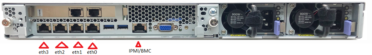
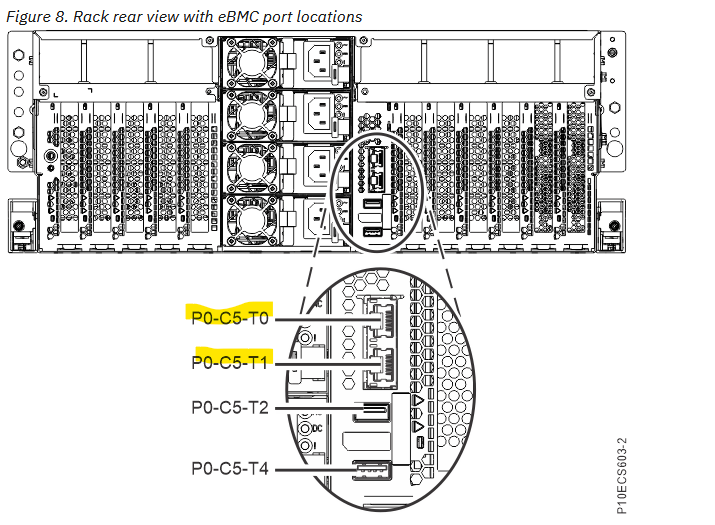
![]() Power10 Servers
Power10 Servers
9105-41B, 9105-42A, or 9786-42H
|
POWER9 Servers
|
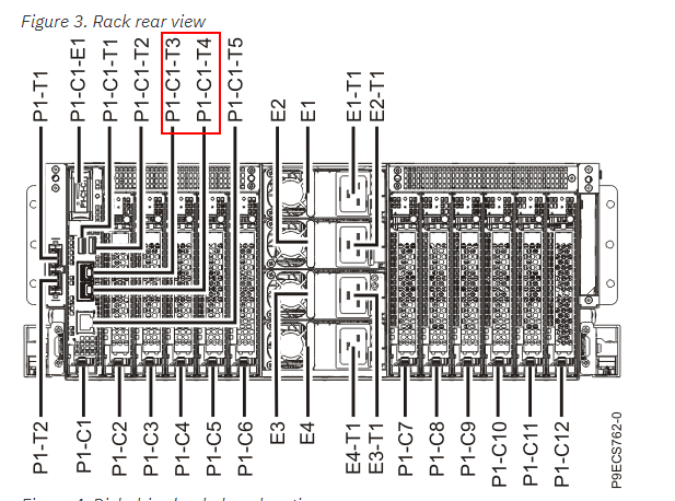
9080-M9S
9040-MR9
9009-22A, 22G, 9008-22L, 9223-22H, 22S, 5105-22E
9009-41A, 42A, 41G, 42G, 9223-42H, 42S
|
POWER8 Servers
|
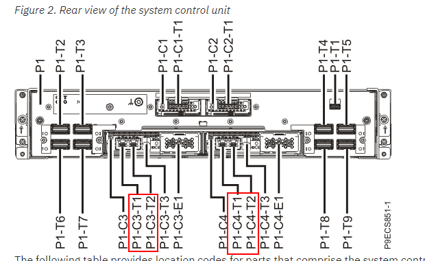
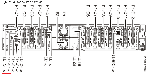
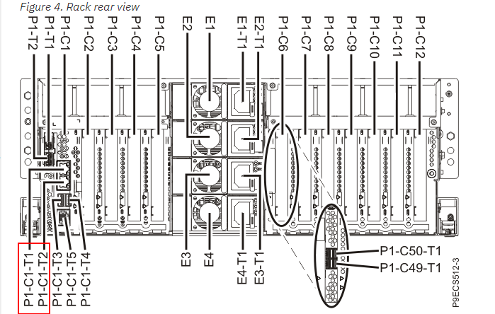
9119 and 9080-MHE and MME
system control unit
Un-P1-C7-T3 Service processor card 1 - HMC port 1
Un-P1-C7-T6 Service processor card 1 - HMC port 2
Un-P1-C10-T3 Service processor card 2 - HMC port 1
Un-P1-C10-T6 Service processor card 2 - HMC port 2
8286 41A and 42A
|
POWER7 Servers
|
Note: On POWER7 Systems, the FSP ports are no longer labeled HMC1 and HMC2.
8231-E1C POWER 710
8231-E2C POWER 730
8202-E4C POWER 720
8205-E6C POWER 740
8202-E4B POWER 720
8205-E6B POWER 740
9117-MMB IBM Power 770
9179-MHB IBM Power 780
9117-MMC/D IBM Power 770
9179-MHC/D IBM Power 780
Note: For multi-enclosure systems, the FSP is active and must be cabled in the top two enclosures.
8233-E8B IBM Power 750 Express
8236-E8C IBM Power 755
9119-FHB
Note: HMC-A (front/P1) and HMC-B (back/P2) Px-C4-J01 port of the Bulk Power Assemblies (BPA).
|
POWER6 Servers
|
View of POWER6 525 models 9407-M15, 9408-M25, 8203-E4A
View of POWER6 550 models 9409-M50, 8204-E8A
View of POWER6 570 models 8234-EMA, 9117-MMA, and 9406-MMA
|
POWER5 Servers
|
Rear View of a Model 9406-520,515,525 Server
Rear View of a Model 9406-550 Server
Rear View of a Model 9406-570 Server
View of a Model 595
Historical Number
357481422
Was this topic helpful?
Document Information
Modified date:
02 June 2023
UID
nas8N1015834