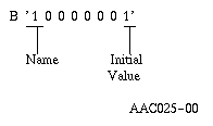
All attributes, specifications, and ODT (object definition table) formats for each non-bound program object in the MI Instruction Set are discussed. Charts illustrate the combinations of attributes and specifications. The detailed formats for the ODV (ODT directory vector) and the OES (ODT entry string) are also specified.
Each Non-Bound Program (NBP) instruction requires from zero to four operands. Each operand may consist of one or more fields that contain either a null operand specification, an immediate data value, or a reference to an ODT object. The size of the operand field depends on the version of the program template. If the version number is 0, the size of the operand field is 2 bytes. If the version number is 1, the size of the operand field is 3 bytes.
Certain instructions allow certain operands to be null. In general, a null operand means that some optional function of the instruction is not to be performed or that a default action is to be performed by the instruction. Note that a null operand is not the same thing as a null pointer value. A null operand is an operand that is specified in the instruction stream as being omitted. The use of a null operand is detectable when the program is being created. In contrast, a null pointer value represents the condition a pointer does not exist at this location. The CMPPTRT instruction can be used to test for a null pointer value. Null pointer values cannot be detected until run time.
The value of this type of operand is encoded in the instruction operand. Immediate operands may have the following values:
This type of operand contains a reference (possibly qualified) to an object in the ODT. Operands that are ODT object references may be simple operands or compound operands.
The value encoded in the operand refers to a specific object defined in the ODT. Simple operands consist of a single 2-byte operand entry.
A compound operand consists of a primary (2-byte) operand and a series of one to three secondary (2-byte) operands. The primary operand is an ODT reference to a base object while the secondary operands serve as qualifiers to the base object.
A compound operand may have the following uses:
An individual element of a data object array, a pointer array, or an instruction definition list may be referenced with a subscript compound operand. The operand consists of a primary reference to the array and a secondary operand to specify the index value to an element of the array.
A portion of a character scalar data object may be referenced as an instruction operand through a substring compound operand. The operand consists of a primary operand to reference the base string object and secondary references to specify the value of an index (position) and a value for the length of the substring.
The length secondary operand field can specify whether to allow or not allow for a null substring reference (a length value of zero).
An instruction operand may specify an explicit override for the base pointer for a based data object or a based addressing object. The operand consists of a primary operand reference to the based object and a secondary operand reference to the pointer on which to base the object for this operand. The override is in effect for the single operand. The displacement implicit in the ODT definition of the primary operand and the addressability contained in the explicit pointer are combined to provide an address for the operand.
The explicit base may be combined with either the subscript or the substring compound operands to provide a based subscript compound operand or a based substring compound operand.
A program template is composed of a header followed by several components, including an instruction stream component and an object definition table (ODT) component. The ODT contains the views of all objects referred to in the instruction stream other than those objects that are immediate value operands in the instructions. The following objects are ODT definable:
The ODV is a vector of 4-byte character string entries in a standard format. An ODV entry describes an object completely or partially. If the ODV entry does not completely describe the object, it must contain an offset into the OES where the object is described completely.
An ODV entry is required for each object described in the ODT. The index value for a particular object ODV entry is used as an operand for instructions that operate on the object. An ODT can contain 8,191 entries in template version 0 and 65,526 entries in template version 1. The first entry has an index value of 1.
The structure of the ODV is designed to allow a complete definition of commonly used objects. An object that cannot be completely described in an ODV entry must have an OES entry to complete its definition.
Each ODV entry generally consists of the following:
The OES consists of a series of variable-length entries that complete an object's description.
If an OES entry exists for an object, its offset value into the OES is specified in the ODV entry for that object.
Several ODV entries for different objects with identical definitions can share the same OES entry. OES entries do not exist for those objects that can be completely described in the ODV.
Each OES entry consists of the following:
For example, assume the following OES header:

The name appendage must immediately follow the OES header, and the initial value appendage must immediately follow the name appendage.
The OES may consist of 0 to 16,776,191 bytes. Because the OES offset value may be a maximum of 65,535 bytes, a means is provided to address an OES offset beyond this maximum. A special object type value (binary 1111) in the ODV denotes an object description in which:
In this section, the detailed definitions for the various ODT entries are discussed by object type. Each object type description contains the following information about its respective objects:
In the attribute combination charts, the following rules are used:
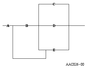
The attribute A can be used with B and C, B and D, B and E, or E only; but C cannot be used with D or E.
| Note: | Reserved bits are those bits not being used currently and should always be set to binary 0. |
Combinations of attributes not defined in these specifications cause a create program exception-invalid ODT exception to be signaled when the program is created.
Data objects provide operational and, possibly, representational characteristics to data in a space. Scalar data objects and pointer data objects are the two basic categories of data contained in the space.
Scalar data objects provide operational and representational characteristics for numeric and character data contained in a space.
Pointer data objects provide operational characteristics for pointer data contained in a space.
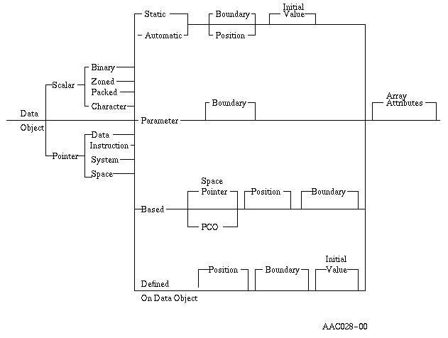
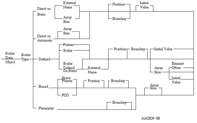
The following chart shows the general characteristics of data objects.
Bits | Meaning | ||||||||||||||||||
0-3 | Object type
| ||||||||||||||||||
4 | OES present
| ||||||||||||||||||
5-7 | Addressability type
All others reserved | ||||||||||||||||||
8 | Optimization of value
| ||||||||||||||||||
9-11 | Boundary
101-111 = Reserved Boundary is assumed to be specified for indirectly addressed program objects. A higher boundary alignment can improve performance when the program object is referenced. | ||||||||||||||||||
12 | System default initial value
| ||||||||||||||||||
13-15 | Scalar type (Group 1)
| ||||||||||||||||||
13-15 | Scalar type (Group 2)
001-111 = Reserved | ||||||||||||||||||
16-31 | OES offset or scalar length
|
Bits | Meaning | ||||
0 | Name and external
| ||||
1 | Scalar length present
| ||||
2 | Array information present
| ||||
3 | Base present
| ||||
4 | Position present
| ||||
5 | Initial value present in OES
| ||||
6 | Replications present in OES
| ||||
7 | OES Header Extension present
|
Bits | Meaning | ||||||
0 | Reserved | ||||||
1 | Extended Scalar Length
| ||||||
2 | Array bounds information present
| ||||||
3-7 | Reserved |
Bytes | Meaning | ||
0-1 | Length (L) of name, where 1 <= L <= 32 | ||
2-L | L characters of symbolic name
|
If Extended Length is not specified in the OES header extension then,
Bytes 0-1 | Scalar length If signed or unsigned binary, then:
|
If Extended Length is specified in the OES header extension then,
Bytes | Meaning |
0-3 | Length (L) of long character string, where 1 <= L <= 16,776,191, except for external strings, where 1 <= L <= 65,535. On prior versions of the machine, longer external strings could be defined, but the apparent length when used (via data pointer reference) was L modulo 65,536. |
Bytes | Meaning |
0-3 | Number (N) of elements in the array, where 1 <= N <= 16,776,191 |
4-5 | Array element offset If the array element offset attribute is specified (bytes 4-5 are nonzero), this field specifies the offset between initial bytes of the elements of a defined on array. |
6-9 | Lower bound of array (LB), |
10-13 | Upper bound of array (UB), The lower bound must be less than or equal to the upper bound. The number of elements in the array is equal to the (UB+1-LB) which must be less than or equal to 16,776,191. |
| Note: | The Lower and Upper bound information is only present if the Array Bounds bit is set in the OES extended header. Arrays of scalar character data objects are only allowed for character data elements whose length is less than or equal to 32,767 characters. |
| Bytes 0-1: | ODT reference for:
|
| Bytes 0-3 | Position value for:
|
Bytes 0-L: | Initial value in format and length as determined by scalar type |
In the initial value appendage, a noncharacter string scalar must have an initial value of the proper size and format (for example, 2-byte binary value for a 2-byte binary scalar).
For arrays and character strings, if the replication bit in the OES is binary 1, the initial value portion must consist of one or more three field components of the following form:
2 bytes: | Number of replications of Associated Value |
2 bytes: | Length (L) of Associated Value |
L bytes: | Associated Value |
| Note: | When the above form is used for specifying the initial values for arrays, the number in the replications field represents the number of array elements to be given the Associated Value. |
The entire object may be initialized contiguously ignoring array element boundaries and byte by byte using the initial value form below.
If the replication bit for an array or a character string whose length is greater than or equal to 32K bytes is binary 0, the initial value appendage must have the following form:
4 bytes: | Length of initial value (less than or equal to the total number of bytes in the array or long character string) |
L bytes: | The initial value of proper size and format to specify the initial values for each element of the array that is to be initialized |
Notes:
Attribute Combinations
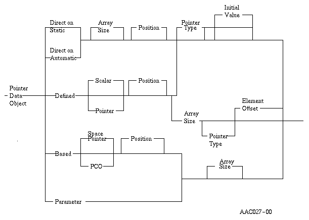
Bits | Meaning | ||||||||||||
0-3 | Object type
| ||||||||||||
4 | OES present
| ||||||||||||
5-7 | Addressability type
All others reserved | ||||||||||||
8 | Optimization of value
| ||||||||||||
9-11 | Reserved | ||||||||||||
12-15 | Pointer type (ignored unless initial value)
All others reserved. Other pointer types cannot have an initial value. | ||||||||||||
16-31 | OES offset
|
Bits | Meaning | ||||
0 | Reserved | ||||
1 | Initial value appendage modifier
| ||||
2 | Array information present
| ||||
3 | Base Present
| ||||
4 | Position present
| ||||
5 | Initial value present
| ||||
6 | Reserved | ||||
7 | OES Header Extension present
|
Bits | Meaning | ||||||
0-1 | Reserved | ||||||
2 | Array bounds information present
| ||||||
3 | Optimization Appendage present
| ||||||
4-7 | Reserved |
Bytes | Meaning |
0-3 | Number (N) of elements in the array, where 1 <= N <= 1,000,000 |
4-5 | Array element offset If the array element offset attribute is specified (bytes 4-5 are nonzero), this field specifies the offset between initial bytes of the pointers of a defined array. Value must be a multiple of 16. |
6-9 | Lower bound of array (LB), where LB is a signed 4-byte integer, minimum value is -2,147,483,648. |
10-13 | Upper bound of array (UB), where UB is a signed 4-byte integer, maximum value is 2,147,483,647. The lower bound must be less than or equal to the upper bound. The number of elements in the array is equal to the (UB+1-LB). |
| Note: | The Lower and Upper bound information is present only when the Array Bounds bit is set in the OES Header Extension. |
| Bytes 0-1: | ODT reference for:
|
| Bytes 0-3: | Position value for:
|
If ODV bits 12-15 indicate instruction pointer:
If the initial value appendage modifier equals 0, the basic format is:
| Bytes 0-1: | Instruction stream reference; indirect
or direct reference to an instruction number
|
| Bytes 0-2: | Instruction stream reference; indirect or direct reference to an
instruction number
Bits 1-7 are reserved (binary 0). |
If ODV bits 12-15 indicate data pointer:
| Bytes 0-1: | Number of names in name list. One or two names may be specified as
the initial value.
| ||||||||||||||||||||||||||||||||||||||||||||||||||||||||||||||||||||||||||||||||||||||||||||||||||||||||||||||||||||||||||||||||||||||||||||||||||||||||||||||||||||||||||||||||||||||||||||||||||||||||||||||||||||||||||||||||||||||||||||||||||||||||||||||||||||||||||
If ODV bits 12-15 indicate space pointer:
Bytes 0-1: | ODT number of a data object or pointer object that is direct or defined on direct. |
| Offset | |||||||||||||
|---|---|---|---|---|---|---|---|---|---|---|---|---|---|
| Dec | Hex |
| Field Name |
| Data Type and Length | ||||||||
| 0 | 0 |
| Number of names (value of 1) |
| Bin(2) | ||||||||
| 2 | 2 |
| Object type code |
| Char(1) | ||||||||
| 3 | 3 |
| Object subtype code |
| Char(1) | ||||||||
| 4 | 4 |
| Minimum authority code |
| Char(2) | ||||||||
| 6 | 6 |
| Object name length (N) |
| Bin(2) | ||||||||
| 8 | 8 |
| Object name string, where 1 <= N <= 30 |
| Char(N) | ||||||||
| * | * |
| --- End --- |
|
| ||||||||
| Offset | |||||||||||||
|---|---|---|---|---|---|---|---|---|---|---|---|---|---|
| Dec | Hex |
| Field Name |
| Data Type and Length | ||||||||
| 0 | 0 |
| Number of names (value of 2) |
| Bin(2) | ||||||||
| 2 | 2 |
| Context type code (value of hex 04) |
| Char(1) | ||||||||
| 3 | 3 |
| Context subtype code |
| Char(1) | ||||||||
| 4 | 4 |
| Context name length (M) |
| Bin(2) | ||||||||
| 6 | 6 |
| Context name string, where 1 <= M <= 30 |
| Char(M) | ||||||||
| * | * |
| Object type code |
| Char(1) | ||||||||
| * | * |
| Object subtype code |
| Char(1) | ||||||||
| * | * |
| Minimum authority code |
| Char(2) | ||||||||
| * | * |
| Object name length (P) |
| Bin(2) | ||||||||
| * | * |
| Object name string, where 1 <= P <= 30 |
| Char(P) | ||||||||
| * | * |
| --- End --- |
|
| ||||||||
Notes:
| Code (Hex) | Object Type |
| 01 | Access group |
| 02 | Program |
| 03 | Module |
| 04 | Context |
| 06 | Byte string space |
| 07 | Journal space |
| 08 | User profile |
| 09 | Journal port |
| 0A | Queue |
| 0B | Data space |
| 0C | Data space index |
| 0D | Cursor |
| 0E | Index |
| 0F | Commit block |
| 10 | Logical unit description |
| 11 | Network description |
| 12 | Controller description |
| 13 | Dump space |
| 14 | Class-of-service description |
| 15 | Mode description |
| 16 | Network interface description |
| 17 | Connection list |
| 18 | Queue space |
| 19 | Space |
| 1A | Process control space |
| 1B | Authority list |
| 1C | Dictionary |
| 1D | Auxiliary server |
| 1E | Byte stream file |
| 23 | Transaction control structure |
| Bit | Meaning |
| 0 | Object control |
| 1 | Object management |
| 2 | Authorized pointer |
| 3 | Space authority |
| 4 | Retrieve |
| 5 | Insert |
| 6 | Delete |
| 7 | Update |
| 8 | Ownership |
| 9 | Excluded |
| 10 | Authority list management |
| 11 | Execute |
| 12 | Alter |
| 13 | Reference |
| 14-15 | Reserved (binary 0) |
A value of binary 1 indicates that the object must have the specified authority in order for resolution to be performed. Zero or more authority bits may be specified, and if any are specified, all must be satisfied.
Reserved bits must have a value of binary 0.
A pointer with based addressability need not have a base specified. If a base is specified, the pointer can, in turn, be based on another pointer. An exception is signaled if the final pointer in the chain is not direct, is not defined on a direct data object, is not a parameter, or is not defined on a parameter. An exception is signaled if a base pointer in the chain is based on a pointer that was previously specified in the chain of based pointers.
The last initialized pointer data object appearing in the ODT for a given storage location overlays all previous pointer object initial values for that location.
The following notes apply to all declarations of data objects, scalars, and pointers. The term data object applies to either scalar data objects or pointer data objects unless explicitly qualified.
Notes:
If more than one data object initializes the same byte (or bytes) in a space, the value associated with the data object appearing last in the ODT overlays the others.
Two examples follow:
| These ODT entries | Would be treated as these: |
| A Char(2) Direct Static | A Char(2) Direct Static Pos(1) |
| B Pkd(3,3) Direct Static | B Pkd(3,3) Direct Static Pos(3) |
| D Pointer Direct Static | D Pointer Direct Static Pos(17). |
| These ODT entries | Would be treated as these: |
| A Char(4) Direct Static | A Char(4) Direct Static Pos(1) |
| B Char(4) Direct Static Pos(20) | B Char(4) Direct Static Pos(20) |
| C Char(4) Direct Static | C Char(4) Direct Static Pos(24) |
| D Char(4) Direct Static Pos(10) | D Char(4) Direct Static Pos(10) |
| E Char(2) Defined B | E Char(2) Direct Static Pos(20) |
| F Char(3) Direct Static | F Char(3) Direct Static Pos(28). |
The default value for the position depends on whether the boundary attribute is specified. Pointer objects always have a default boundary attribute that is a multiple of 16.
A boundary specification for a direct data object causes the data object to be located at the next available position having an offset value that is a multiple of the boundary specified. If boundary is specified, a value may not be specified for the position attribute. The boundary specification for a direct pointer object is always a multiple of 16. A position specified for a direct pointer object must be a multiple of 16.
If neither position nor boundary is specified for a direct data object, the object is located at the next available position without regard to boundary alignment.
The size for the static and automatic spaces can also be defaulted if the size of static (automatic) storage entry in the program template is 0. The value used is such that the space is large enough to contain all data objects with defaulted and explicit direct mapping. An exception is signaled if a size that is insufficient to contain defaulted and direct mapped data objects is specified.
To summarize, the rules related to positioning data objects and setting of the size through defaulted directed data objects are:
Attribute Combinations
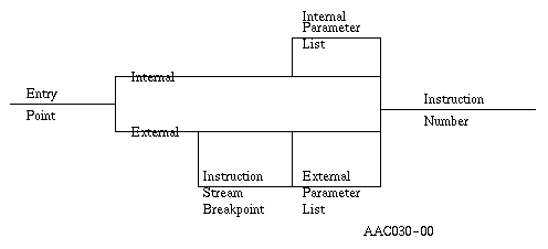
Bits | Meaning | ||||
0-3 | Object type
| ||||
4 | OES present
| ||||
5-14 | Reserved (binary 0) | ||||
15 | Scope
| ||||
16-31 | OES offset or entry point value OES offset if OES present (bit 4=1). Entry point value equals the instruction number if no entry point parameters are listed |
Bits | Meaning | ||||
0 | Instruction stream breakpoint
| ||||
1-2 | Reserved (binary 0) | ||||
3 | Parameter information present
| ||||
4-6 | Reserved (binary 0) | ||||
7 | Initial value present
|
| Bytes 0-1 | Instruction number for instruction stream breakpoint identifies first instruction of half of program that is not executed in the normal path |
| Bytes 0-1 | ODT reference for operand list describing entry point parameters |
| Bytes 0-1 | Instruction number for entry point |
Notes:
Attribute Combinations

Bits | Meaning | ||
0-3 | Object type
| ||
4 | OES present
| ||
5-15 | Reserved (binary 0) | ||
16-31 | Value Instruction number (N) of branch point, where 1 <= N <= 65,535. |
No OES is needed for branch points.
Attribute Combinations

Bits | Meaning | ||
0-3 | Object type
| ||
4 | OES present
| ||
5-15 | Reserved (binary 0) | ||
16-31 | OES offset |
Bits | Meaning | ||||
0 | Reserved (binary 0) | ||||
1 | Initial value appendage modifier
| ||||
2-6 | Reserved (binary 0) | ||||
7 | Initial value present
|
Bytes | Meaning |
0-1 | Number (N) of list elements, where 1 <= N <= 255 |
If the initial value appendage modifier equals 0, the basic format:
2-3 | Instruction reference element 1 |
.
.
.
| X-X+1 | Instruction reference element N |
| 2-4 | Instruction reference element 1 |
.
.
.
| X-X+1 | Instruction reference element N |
| Note: | An instruction reference element has the following formats: |
If the initial value appendage modifier equals 0, the basic format is:
Bytes 0-1: | Instruction stream reference; indirect or direct reference to an instruction number
|
Bytes 0-2: | Instruction stream reference; indirect or direct reference to an instruction number
|
Attribute Combinations
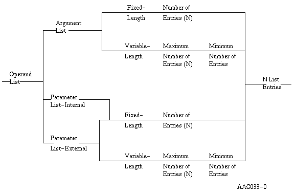
Bits | Meaning | ||||||||
0-3 | Object type
| ||||||||
4 | OES present
| ||||||||
5 | Argument list
| ||||||||
6-7 | Parameter list (if not binary 0, bit 5 must be binary 0)
| ||||||||
8 | Length attribute
| ||||||||
9-15 | Reserved (binary 0) | ||||||||
16-31 | OES offset OES offset = OES is always present |
Bits | Meaning | ||
0-6 | Reserved (binary 0) | ||
7 | Initial value present
|
Bytes | Meaning | ||||||||||||
0-3 | Number (N) of list elements, where 1 <= N <= 255
| ||||||||||||
4-5 | ODT reference 1 . . . |
X-X+1 | ODT reference N N elements are required. |
Notes:
Attribute Combination

Bits | Meaning | ||||||||||||||||||||||
0-3 | Object type
| ||||||||||||||||||||||
4 | OES present
| ||||||||||||||||||||||
5 |
| ||||||||||||||||||||||
6 | Value in bits 8-15
| ||||||||||||||||||||||
7 | Reserved (binary 0) | ||||||||||||||||||||||
8-15 | Value specification
| ||||||||||||||||||||||
16-31 | OES offset or scalar length
|
Bits | Meaning | ||||
0 | Reserved (binary 0) | ||||
1 | Length information present
| ||||
2-5 | Reserved (binary 0) | ||||
6 | Value present
| ||||
7 | Replications present in OES
|
Bytes | Meaning | ||||||||||||||
0-1 | Scalar length
|
| Bytes 0-L: | Value in format and length as determined by constant data object
scalar type.
If the replication attribute is binary 0, the value for a character constant view is a byte string of length equal to the object length. |
Attribute Combinations
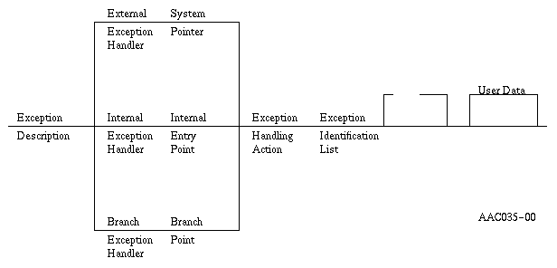
Bits | Meaning | ||||||||||||
0-3 | Object type
| ||||||||||||
4 | OES present
| ||||||||||||
5 | Return exception data
| ||||||||||||
6-7 | Reserved (binary 0) | ||||||||||||
8-9 | Exception handler type
| ||||||||||||
10-12 | Exception handling action
110-111 = Reserved | ||||||||||||
13-15 | Reserved (binary 0) | ||||||||||||
16-31 | OES offset (required) |
Bits | Meaning | ||||
0 | Target
| ||||
1 | Target appendage modifier
| ||||
2-4 | Reserved (binary 0) | ||||
5 | Compare value
| ||||
6 | User data
| ||||
7 | Exception identifications
|
For external and internal entry point exception handlers the target appendage modifier must be 0. The appendage has the following form:
| Bytes 0-1: | ODT reference to
|
For branch point exception handlers the target appendage has the following form:
If the initial value appendage modifier equals 0, the basic format is:
Bytes 0-1: | Instruction stream reference; indirect or direct reference to an instruction number.
|
Bytes 0-2: | Instruction stream reference; indirect or direct reference to an instruction number.
|
| Bytes 0-1 | ODT reference to either
|
Bytes | Meaning |
0-1 | Compare value length (maximum value of 32) |
2-N | Compare value |
Bytes | Meaning |
0-1 | Number (N) of exception numbers |
2-(2n + 1) | N 2-byte exception numbers |
Notes:
Bits | Meaning | ||
0-3 | Object type
| ||
4-7 | Reserved (binary 0) | ||
8-31 | OES offset (3 bytes) |
Bytes | Meaning |
0-1 | First 2 bytes of standard ODV entry for this object |
2 | OES header for this object |
3-N | OES appendages for this object |
Attribute Combinations

Bits | Meaning | ||||
0-3 | Object type
| ||||
4 | OES present
| ||||
5-11 | Reserved (binary 0) | ||||
12-15 | Pointer type(required)
| ||||
16-31 | OES offset
|
Bits | Meaning | ||||
0-4 | Reserved (binary 0) | ||||
5 | Initial value present
| ||||
6 | Optimization priority value present
| ||||
7 | Reserved (binary 0) |
If ODV bits 12-15 indicate space pointer:
Bytes 0-1: | ODT number of a data object or pointer object that is direct or defined on direct. |
Bytes | Meaning | ||||
0 | Optimization priority value.
| ||||
1-3 | Reserved (binary 0) |
Normally, optimizations are performed on pointers according to a priority established by a machine analysis of pointer usage within the program. The optimization priority attribute allows a space pointer machine object to be given a priority attribute which overrides the normal prioritization of space pointer machine objects performed by the machine when programs are created. Through this facility, space pointer machine objects can be specified as being of high optimization priority even though the analysis performed by the machine would determine the space pointer machine object to be of low usage within the program. Specifying a priority value indicates that the pointer is of higher priority than those with a lower value or those for which no value is specified. A particular priority value can be specified for multiple pointers to indicate that they are of equal priority relative to each other.
The number of space pointer machine objects for which special optimizations can be done is quite low, normally 2 or 3 (maximum of 12) depending on the particular program. The number of space pointer machine objects that can be specified in the program is limited by the amount of storage available for them in the internal work space associated with the program.
Space pointer machine objects are allowed in the ODV component of the program template only as an optimization option. This is because of the additional processing overhead necessary to provide support for them during program creation.
If no priority attribute is specified, the normal prioritization of space pointer data objects and space pointer machine objects controls the optimizations performed on them. When the priority attribute is specified, the effect it may have on the optimizations being performed is dependent upon the particular implementation of the machine. A beneficial effect may only be realized for some of the pointers carrying the attribute due to constraints on the optimizations which can be performed for a particular machine.
Abnormal modification of space pointer machine objects is not supported. That is, the abnormal attribute supported for space pointer data objects is not allowed for space pointer machine objects. Cases of abnormal pointer modification (those which can violate the addressability fetching optimizations performed by Create Program) can not be accomplished through use of a space pointer machine object. Such cases must be provided for through usage of a space pointer data object which has been defined with the abnormal attribute.
The particular area of exposure for usage of space pointer machine objects is the case of modification of the pointer value during the execution of an internal exception handler. In this case, resuming execution of the program after the exception handler returns may continue using the prior rather than the newly modified value of the pointer. Other abnormal modifications which apply to usage of space pointer data objects do not apply to space pointer machine objects. This is because defined on views of and external program modification of space pointer machine objects is not supported.
Each Non-Bound Program (NBP) instruction requires from zero to four operands. Each operand may consist of one or more fields that contain either a null operand specification, an immediate data value, or a reference to an ODT object. The size of the operand field depends on the version of the program template. If the version number is 0, the size of the operand field is 2 bytes. If the version number is 1, the size of the operand field is 3 bytes.
Certain instructions allow certain operands to be null. In general, a null operand means that some optional function of the instruction is not to be performed or that a default action is to be performed by the instruction. Note that a null operand is not the same thing as a null pointer value. A null operand is an operand that is specified in the instruction stream as being omitted. The use of a null operand is detectable when the program is being created. In contrast, a null pointer value represents the condition a pointer does not exist at this location. The CMPPTRT instruction can be used to test for a null pointer value. Null pointer values cannot be detected until run time.
The value of this type of operand is encoded in the instruction operand. Immediate operands may have the following values:
This type of operand contains a reference (possibly qualified) to an object in the ODT. Operands that are ODT object references may be simple operands or compound operands.
The value encoded in the operand refers to a specific object defined in the ODT. Simple operands consist of a single 2-byte operand entry.
A compound operand consists of a primary (2-byte) operand and a series of one to three secondary (2-byte) operands. The primary operand is an ODT reference to a base object while the secondary operands serve as qualifiers to the base object.
A compound operand may have the following uses:
An individual element of a data object array, a pointer array, or an instruction definition list may be referenced with a subscript compound operand. The operand consists of a primary reference to the array and a secondary operand to specify the index value to an element of the array.
A portion of a character scalar data object may be referenced as an instruction operand through a substring compound operand. The operand consists of a primary operand to reference the base string object and secondary references to specify the value of an index (position) and a value for the length of the substring.
The length secondary operand field can specify whether to allow or not allow for a null substring reference (a length value of zero).
An instruction operand may specify an explicit override for the base pointer for a based data object or a based addressing object. The operand consists of a primary operand reference to the based object and a secondary operand reference to the pointer on which to base the object for this operand. The override is in effect for the single operand. The displacement implicit in the ODT definition of the primary operand and the addressability contained in the explicit pointer are combined to provide an address for the operand.
The explicit base may be combined with either the subscript or the substring compound operands to provide a based subscript compound operand or a based substring compound operand.