IBM Integration Bus, Version 9.0.0.8 Operating Systems: AIX, HP-Itanium, Linux, Solaris, Windows, z/OS

See information about the latest product version

SCAAsyncResponse node

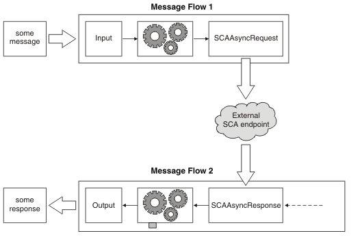
Use the SCAAsyncResponse node with the SCAAsyncRequest node to construct a pair of message flows that start a component asynchronously.

Purpose

The node allows the broker to receive the response to a previous asynchronous request made from an SCAAsyncRequest node.

Diagram showing the relationship between the SCAAsynchronousRequest node and the SCAAsynchronousResponse node.

The node is contained in the SCA drawer of the palette, and is represented in the IBM® Integration Toolkit by the following icon:

SCAAsyncResponse node icon

Using this node in a message flow

Look at the following sample to see how to use the node:

You can view information about samples only when you use the product documentation that is integrated with the IBM Integration Toolkit or the online product documentation. You can run samples only when you use the product documentation that is integrated with the IBM Integration Toolkit.

You can retrieve context data that has been stored by the SCAAsyncRequest node from the following location in the local environment:

LocalEnvironment.SCA.Response.UserContext

You can access the SOAP header and context information in an inbound response in the local environment, at the following locations:

LocalEnvironment.SCA.Response.Binding.WebServices.SOAP.Header
LocalEnvironment.SCA.Response.Binding.WebServices.SOAP.Context

Configuring the node

Ensure that the message set contains a Broker SCA definition with an extension of .outsca with which to configure the node.

There are two methods of putting an instance of the node into a message flow: You can either drag an instance of the node from the node palette, or drag a Broker SCA definition with an extension of .outsca from a message set, onto the message flow editor canvas. Dragging a Broker SCA definition with an extension of .outsca onto the canvas creates a pair of SCAAsyncRequest and SCAAsyncResponse nodes.

If you have dragged an instance of the node from the palette onto the canvas, you must then start to configure it by dragging a Broker SCA definition with an extension of .outsca onto the node. The values for many of the node properties are provided in the Broker SCA definition. If you have dragged a Broker SCA definition onto the canvas and created a pair of SCAAsyncRequest and SCAAsyncResponse nodes, many of the values for the node properties have already been supplied from the Broker SCA definition.

The properties of the node are displayed in the Properties view. All mandatory properties for which you must enter a value (properties that do not have a default value defined) are marked with an asterisk.

  1. Optional: On the Description tab, enter a Short description, a Long description, or both. You can also rename the node on this tab.
  2. On the Basic tab, set the Unique identifier and Broker SCA definition properties.
    • Unique identifier. You must specify the unique URL fragment that is common to your pair of SCAAsyncRequest and SCAAsyncResponse nodes. This property is mandatory.
    • In Broker SCA definition, specify the name of the Broker SCA definition that contains configuration properties for the node. If you have created the node by dragging a Broker SCA definition from a message set onto the Message flow editor canvas, this property is preset to the name of the Broker SCA definition. If you created the node by selecting it from the palette, you can set this property in one of the following ways:
      • If you have a Broker SCA definition, you can select it from the Broker SCA definitions by clicking Browse.
      • If you have Broker SCA definitions, but no message set, you can create a message set:
        1. Click Browse to open the Broker SCA Definition Selection pane.
        2. Click Import/Create New to open the Import Broker SCA definition wizard.
        3. Enter the message set name and message set project name, then click Next.
        4. Choose the relevant option:
          • If your Broker SCA definition exists in your workspace, click Use resources from the workspace, and select the Broker SCA definition.
          • If your Broker SCA definition is in the file system, click Use external resources, select the Broker SCA definition, then click Next.
        5. Select the Broker SCA definition to import.
        6. Click Finish. A new message set project and message set are created with message definitions. The Broker SCA definition is added to the Broker SCA Definitions folder.
        7. Select the Broker SCA definition from the Broker SCA Definition Selection window, then click OK.
      • If you have a message set but no Broker SCA definition, generate a Broker SCA definition by following the instructions in Message Sets: Generating a Broker SCA definition from a message set.
      • Drag a Broker SCA definition from a message set onto the node.
      • Type a file name that is relative to the message set project in which the Broker SCA definition exists.
  3. On the Binding tab, specify properties that relate to the binding. Some of the properties on this tab are derived from the Broker SCA definition.
    The value of the Binding type property is derived from the binding information in the Broker SCA definition, and is read-only. Possible values are:
    • WebService. Web service responses are sent as SOAP messages over the HTTP transport.
    • MQ. MQ responses arrive as messages.

    The Propagate only SOAP body (owned by XMLNSC domain) check box is shown only when the Binding type is Web Services. It is not shown when the Binding type is MQ; there are no MQ-specific binding properties.

  4. On the Response Message Parsing tab, the properties are set automatically from the Broker SCA Definition file.
    • If the Binding type is Web Services, the Message domain is always SOAP. If the Binding type is MQ, you can change the domain to MRM, XMLNSC, XMLNS, MIME, JSON, DFDL, or BLOB.
    • If the Binding type is MQ, the Message domain defaults to XMLNSC if the data bindings for all operations are using XML. Otherwise the default domain is BLOB.
  5. On the Parser Options sub tab, set properties that are associated with the parser.
    • Parse timing is, by default, set to On Demand, which causes parsing of the message to be delayed. For information about how to cause the message to be parsed immediately, see Parsing on demand.
    • XMLNSC Parser Options. Set values for the properties that determine how the XMLNSC parser operates. For more information, see Manipulating messages in the XMLNSC domain.
  6. Use the Validation tab to provide validation based on the message set for predefined messages. For more information about validation, see Validating messages. For information about how to complete this tab, see Validation tab properties.
  7. Use the Instances tab to specify how additional threads are handled for the message flow.
    • The Additional instances pool property specifies whether additional instance threads are allocated from a thread pool for the whole message flow, or from a thread pool for use by that node only. By default, this property is set to Use Pool Associated with Message Flow.
    • The Additional instances property specifies the number of additional threads that the broker can use to service the message flow and has the default value 0.

Terminals and properties

The terminals of the node are described in the following table.

Terminal Description
Failure The output terminal to which the message is routed if a failure is detected when the message is propagated.
Out The output terminal to which the message is routed if it has been propagated successfully, and if further processing is required within this message flow.
Fault The output terminal to which a SOAP fault message is routed if the Binding type is Web Services. The Fault terminal is not used by any other type of Binding type.
Catch The output terminal to which the message is routed if an exception is thrown downstream and caught by this node.

When you have put an instance of the node into a message flow, you can configure it; see Configuring a message flow node. The properties of the node are displayed in the Properties view. All mandatory properties for which you must enter a value (properties that do not have a default value defined) are marked with an asterisk.

The following tables describe the node properties. The column headed M indicates whether the property is mandatory (marked with an asterisk if you must enter a value when no default is defined); the column headed C indicates whether the property is configurable (you can change the value when you add the message flow to the BAR file to deploy it).

The Description properties of the node are described in the following table.

Property M C Default Description
Node name No No The node type: SOAPAsyncResponse The name of the node.
Short description No No None A brief description of the node.
Long description No No None Text that describes the purpose of the node in the message flow.

The Basic properties of the node are described in the following table:

Property M C Default Description
Unique identifier Yes No Not set Specify the unique identifier that is common to your pair of nodes.
Broker SCA definition Yes Yes Not set The property specifies the name of the Broker SCA definition that contains configuration properties for the node. You can click Browse to see a list of all relevant Broker SCA definitions in the current workspace.
.
The Binding properties of the node are described in the following table:
Property M C Default Description
Binding type Yes No Not set The binding type that was found in the SCA Import.
extractSOAPBody No No Cleared This option is available if the binding is Web Services. If the check box is selected, only the SOAP body is propagated. If it is cleared, the entire SOAP message is propagated.

The Response Message Parsing properties of the node are described in the following table. The node sets these properties automatically; the table describes when you can change them.

Property M C Default Description
Message domain No No Set automatically according to the binding that is defined in the corresponding node. The domain that is used to parse the response message. It is determined according to the Binding type. You can change this property if the Binding type is MQ. The property is read-only when the Binding type is Web Services.
Message model No No Picked automatically according to the Broker SCA definition that is chosen in the corresponding node. The name or location of the message model in which the response message is defined. The Message model is set automatically to the message model that contains the SCA file that is configured on the corresponding node. This property is read-only.
Message No No Picked automatically according to the Broker SCA definition that is chosen in the corresponding node. The node detects the message automatically. You can change this property if the Binding type is MQ and the message domain is MRM. You cannot change this property if the Binding type is Web Services.
Physical Format No No   The name of the physical format of the response message. You can change this property if the Binding type is MQ and the message domain is MRM. You cannot change this property if the Binding type is Web Services.

The Parser Options properties of the node are described in the following table.

Property M C Default Description
Parse timing Yes No On Demand This property controls when a response message is parsed. Valid values are On Demand, Immediate, and Complete.

By default, parse timing is set to On demand, which causes parsing of the input message to be delayed. For a full description of this property, see Parsing on demand.

Build tree using XML schema data types No No Selected This property controls whether the XMLNSC parser creates syntax elements in the message tree with data types taken from the XML Schema.
Retain mixed content Yes No Cleared This property controls whether the parser creates elements in the message tree when it encounters mixed text in a response message. If you select the check box, elements are created for mixed text. If the check box is cleared, mixed text is ignored and no elements are created.
Retain comments Yes No Cleared This property controls whether the parser creates elements in the message tree when it encounters comments in a response message. If you select the check box, elements are created for comments. If the check box is cleared, comments are ignored and no elements are created.
Retain processing instructions Yes No Cleared This property controls whether the parser creates elements in the message tree when it encounters processing instructions in a response message. If you select the check box, elements are created for processing instructions. If the check box is cleared, processing instructions are ignored and no elements are created.
Opaque elements No No Not set This property is used to specify a list of elements in the response message that are to be opaquely parsed. Opaque parsing is performed only if validation is not enabled (that is, if Validate is None); entries that are specified in Opaque Elements are ignored if validation is enabled.

The Validation properties of the node are described in the following table.

If validation fails, the message is propagated to the failure terminal, if this terminal is wired. For more details, see Validating messages and Validation properties.

Property M C Default Description
Validate Yes Yes Content and value This property controls whether validation takes place. Valid values are None, Content and value, and Content.
Failure action Yes Yes Exception This property controls what happens if validation fails. You can set this property only if you set Validate to Content or Content and value. Valid values are User trace, Exception list, Local error log, and Exception.
The Security properties of the node are described in the following table. Set values for these properties to control the extraction of an identity from a message (when a security profile is associated with the node). For more information about these properties, see Identity, Configuring the extraction of an identity or security token, Message flow security overview, and Setting up message flow security.
Property M C Default Description
Identity token type No No None This property specifies the type of identity token present in the incoming message. Valid values are: Transport Default, Username, Username + Password, SAML Assertion, and X.509 Certificate. If this property is not specified, the identity is retrieved from the Basic-Auth transport header and the type is set to Username + Password.
Identity token location No No None This property specifies where, in the message, the identity can be found. The location is specified as an ESQL field reference, an XPath expression, or a string literal. If you use a string literal, it must be enclosed in single quotation marks and must not contain a period (.), If this property is not specified, the identity is retrieved from the MQMD.UserIdentifier transport header.
Identity password location No No None This property specifies where, in the message, the password can be found. The location is specified as an ESQL field reference, an XPath expression, or a string literal. If you use a string literal, it must be enclosed in single quotation marks and must not contain a period (.), If it is not specified, the password is not set. This property can be set only if Identity token type is set to Username + Password.
Identity IssuedBy location No No None This property specifies a string or path expression that describes the issuer of the identity. The location is specified as an ESQL field reference, an XPath expression, or a string literal. If you use a string literal, it must be enclosed in single quotation marks and must not contain a period (.), The value specifies the Issuer that is passed to a WS-Trust v1.3 STS provider. If this property is not specified, the MQMD.PutApplName value is used. If you leave the Identity issuedBy location field blank and the MQMD.PutApplName is also blank, the string MQ is used.
Treat security exceptions as normal exceptions No No False This property specifies whether to treat security exceptions (such as "Access Denied") as normal exceptions, and propagate them to the Failure terminal (if wired). This property is turned off by default, which ensures that security exceptions cause the message to be backed out even if the Failure terminal is wired.

The Instances properties of the node are described in the following table.

Property M C Default Description
Additional instances pool No Yes Flow The pool from which additional instances are obtained.
  • If you select Flow, additional instances are obtained from the message flow value.
  • If you select Node, additional instances are allocated from the additional instances pool for that node; how many are allocated is specified in the Additional instances property.
Additional instances No Yes 0 The number of additional instances that the node can start if the Additional instances pool property is set to Node. By default, no additional instances are given to the node.
The Monitoring properties of the node are described in the following table.
Property M C Default Description
Events No No None Events that you have defined for the node are displayed on this tab. By default, no monitoring events are defined on any node in a message flow. Use Add, Edit, and Delete to create, change or delete monitoring events for the node; see Configuring monitoring event sources using monitoring properties for details.

You can enable and disable events that are shown here by selecting or clearing the Enabled check box.


ac68540_.htm | Last updated Friday, 21 July 2017