This information includes examples of panels that are used to define IQD channels and devices for z/OS® Communications Server using HCD.
- Select processors Figure 1. Select processors

- Select 'S' Work with attached channel paths Figure 2. Work with attached channel paths

- On the Channel Path List enter the Add command (or press F11)
to initiate the Define Channel Path dialog. Figure 3. Initiate the Define Channel Path dialog

- Fill in the Add Channel Path panel, then press Enter (Select SHR
for Operation mode to share IQD Chpids across LPARs). Figure 4. Add channel path

- For an IQD channel path, the Specify Maximum Frame Size panel
pops up with the default value of 16 KB. Figure 5. Specify Maximum Frame Size

Or change the frame size to wanted size:
Table 1. Frame size specification Maximum Frame Size TCP/IP MTU size 16K 8K 24K 16K 40K 32K 64K 56K - Define the channel path access list that each LPAR should have
access to. Figure 6. Define the channel path access list

- Having pressed Enter, the Channel Path List is redisplayed with
channel path number FF defined. Figure 7. Channel path number FF defined

- As the next step, add the control unit(s) to the IQD channel path.
Select the defined channel path with action "Work with attached control
units" (action code 'S'). Figure 8. Work with attached control units

- An empty control unit list is displayed. Enter the 'Add' command
or F11. Figure 9. Add the control unit(s)

- Define a control unit of type 'IQD' for channel path FF. Figure 10. Define a control unit

- Define it to the processor: Figure 11. Define it to the processor

- The processor settings are already preset. Pressing Enter, returns
to the Select Processor/Control unit panel. Pressing Enter again,
returns to the Control Unit List panel which shows the currently defined
control unit. Figure 12. Currently defined control unit

- Next, define the devices. Successively, select a control unit
and perform action "Work with attached Devices". Figure 13. Define the devices

- This leads to an empty device list. Figure 14. Empty device list

- Perform the Add action to define the devices for the control unit
selected in the previous step. Figure 15. Define the devices for the control unit

- Add devices of type IQD to the selected control unit. Figure 16. Add devices of type IQD

- If the number of devices has been left unspecified (as in this
example), HCD defines 10 devices. Figure 17. Define number of devices

- Hit enter and the next panel displayed will be: Figure 18. Define device to operating system

- Next, define the devices to the operating system by selecting
an 'S' on each system you want to have them defined on. Figure 19. Select systems

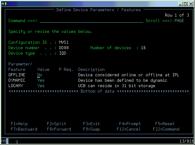
- The device parameters are shown with default values. Press Enter,
to complete the definition for each system. Figure 20. Complete the definition

- Press Enter until you return to the I/O device list panel, the
definition for channel path FF is complete. Figure 21. Definition completed

The sample IOCP input for this example would be:
----+----1----+----2----+----3----+----4----+----5----+----6----+----7--
         CHPID PATH=(FF),SHARED,                                       *
               PARTITION=((LPAR1,LPAR2,LPAR3),(LPAR1,LPAR2,LPAR3)),    *
               TYPE=IQD,OS=00
         CNTLUNIT CUNUMBR=DD00,PATH=(FF),UNIT=IQD
         IODEVICE ADDRESS=(DD00,010),CUNUMBR=(DD00),UNIT=IQD