IBM® DB2® pureScale® Feature supports multiple communication adapter ports on
the cluster caching facilities (CFs) and members.
Multiple communication adapter ports enable DB2 support
of network topologies with either one or two switches. A one-switch multiple communication adapter port configuration
increases the throughput of requests. A two-switch configuration helps
with increased throughput and high availability. DB2 pureScale environments
do not require multiple communication
adapter ports however, multiple
communication adapter ports do help with resiliency and high
availability.
Requirements for using multiple
communication adapter ports
Multiple
communication adapter ports are supported by
DB2 pureScale Feature in
the one-switch and two-switch configurations. The rules that apply
to both configurations are as follows:
One-switch configuration with
multiple communication adapter ports
All
CF and
member hosts in a one-switch configuration are connected to the same
switch by
multiple communication adapter
ports. The one-switch configuration is the simplest
DB2 pureScale environment
with
multiple communication adapter
ports to set up. The redundant
communication
adapter ports connecting each
CF or
member to
the switch increases the bandwidth and the redundant adapter ports
improve fault tolerance in the event one of the links fail. As long
as a
CF or
member has
one functional
communication adapter
port and a public Ethernet connection the
CF or
member remains
operational. The following table is one-switch network topology example
with
multiple communication adapter
ports to each
CFs.
Table 1. Multiple
communication adapter ports on CF hosts and members with 1 switch| Host |
Cluster inter-connect adapter |
Adapter port |
Network interface name |
Cluster interconnect netname |
IP address |
Subnetwork mask (Netmask) |
Subnet |
|---|
| PrimaryCF |
iba0 |
0 |
ib0 |
PrimaryCF-netname1 |
10.111.0.1 |
255.255.255.0 |
10.111.0.0 |
| PrimaryCF |
iba0 |
1 |
ib1 |
PrimaryCF-netname2 |
10.111.1.1 |
255.255.255.0 |
10.111.1.0 |
| PrimaryCF |
iba1 |
0 |
ib2 |
PrimaryCF-netname3 |
10.111.2.1 |
255.255.255.0 |
10.111.2.0 |
| PrimaryCF |
iba1 |
1 |
ib3 |
PrimaryCF-netname4 |
10.111.3.1 |
255.255.255.0 |
10.111.3.0 |
| SecondaryCF |
iba0 |
0 |
ib0 |
SecondaryCF-netname1 |
10.111.0.2 |
255.255.255.0 |
10.111.0.0 |
| SecondaryCF |
iba0 |
1 |
ib1 |
SecondaryCF-netname2 |
10.111.1.2 |
255.255.255.0 |
10.111.1.0 |
| SecondaryCF |
iba1 |
0 |
ib2 |
SecondaryCF-netname3 |
10.111.2.2 |
255.255.255.0 |
10.111.2.0 |
| SecondaryCF |
iba1 |
1 |
ib3 |
SecondaryCF-netname4 |
10.111.3.2 |
255.255.255.0 |
10.111.3.0 |
| Member0 |
iba0 |
0 |
ib0 |
Member0-netname1 |
10.111.0.101 |
255.255.255.0 |
10.111.0.0 |
| Member0 |
iba1 |
0 |
ib1 |
Member0-netname2 |
10.111.1.101 |
255.255.255.0 |
10.111.1.0 |
| Member1 |
iba0 |
0 |
ib0 |
Member1-netname1 |
10.111.0.102 |
255.255.255.0 |
10.111.0.0 |
| Member1 |
iba1 |
0 |
ib1 |
Member1-netname2 |
10.111.1.102 |
255.255.255.0 |
10.111.1.0 |
| Member2 |
iba0 |
0 |
ib0 |
Member2-netname1 |
10.111.0.103 |
255.255.255.0 |
10.111.0.0 |
| Member2 |
iba1 |
0 |
ib1 |
Member2-netname2 |
10.111.1.103 |
255.255.255.0 |
10.111.1.0 |
| Member3 |
iba0 |
0 |
ib0 |
Member3-netname1 |
10.111.0.104 |
255.255.255.0 |
10.111.0.0 |
| Member3 |
iba1 |
0 |
ib1 |
Member3-netname2 |
10.111.1.104 |
255.255.255.0 |
10.111.1.0 |
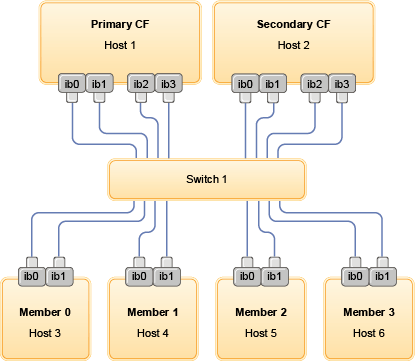
Figure 1. The 2 CFs and
four members connect to one switch.
Note: Because
IPoIB uses different address resolution protocol than other traditional
interconnect (such as Ethernet), there is no requirement and benefit
of putting members in different IP subnets in terms of availability
of members in the case of adapter or switch failure.
Two-switch configuration with
multiple communication adapter ports
The two-switch configuration
improves network resiliency over the one-switch configuration. If
a switch fails, the second switch reduces the risk of a critical failure.
Additional setup requirements for a two-switch configuration are as
follows:
- Half of the communication adapter
ports must be connected to each switch.
- The switches must be connected to each other by two or more inter-switch
links. Connect the two switches together by half the total number
of cables that connect CFs and
members, members to
the switches to improve bandwidth and fault tolerance.
- Switch failover capability must be configured for
the switch so that if one switch fails, the surviving switch and hosts
connected to it are not impacted.
- Distribute the members evenly between the switches so that each
switch is cabled to the same number of members.
Connect each
CF or member adapter
port
with the same IP subnetwork to the same switch.
If both ports of the same physical adapter are used, configure the
adapter interface so that a port from the adapter is connected to
each switch. By connecting to each switch by multiple adapters the
risk posed by a switch or adapter failure is reduced:
- If an adapter of a CF or member fails,
it can still communicate with each switch through the other surviving
adapter, and a subsequent switch failure would not bring down the DB2 pureScale environment.
- If a switch fails, a subsequent adapter failure on a CF would
still leave the primary and secondary CF intact.
The following table is two-switch network topology example with
multiple communication adapter ports to
each
CF and member.
Table 2. Multiple
communication adapter ports on CFs and members with
two switches| Host |
Cluster inter-connect adapter |
Adap-ter port |
Network interface name |
Cluster interconnect netname |
Connected to switch |
IP address |
Subnetwork mask (Netmask) |
Subnet |
|---|
| PrimaryCF |
iba0 |
0 |
ib0 |
PrimaryCF-netname1 |
1 |
10.222.0.1 |
255.255.255.0 |
10.222.0.0 |
| PrimaryCF |
iba0 |
1 |
ib1 |
PrimaryCF-netname2 |
2 |
10.222.1.1 |
255.255.255.0 |
10.222.1.0 |
| PrimaryCF |
iba1 |
0 |
ib2 |
PrimaryCF-netname3 |
1 |
10.222.2.1 |
255.255.255.0 |
10.222.2.0 |
| PrimaryCF |
iba1 |
1 |
ib3 |
PrimaryCF-netname4 |
2 |
10.222.3.1 |
255.255.255.0 |
10.222.3.0 |
| SecondaryCF |
iba0 |
0 |
ib0 |
SecondaryCF-netname1 |
1 |
10.222.0.2 |
255.255.255.0 |
10.222.0.0 |
| SecondaryCF |
iba0 |
1 |
ib1 |
SecondaryCF-netname2 |
2 |
10.222.1.2 |
255.255.255.0 |
10.222.1.0 |
| SecondaryCF |
iba1 |
0 |
ib2 |
SecondaryCF-netname3 |
1 |
10.222.2.2 |
255.255.255.0 |
10.222.2.0 |
| SecondaryCF |
iba1 |
1 |
ib3 |
SecondaryCF-netname4 |
2 |
10.222.3.2 |
255.255.255.0 |
10.222.3.0 |
| Member0 |
iba0 |
0 |
ib0 |
Member0-netname1 |
1 |
10.222.0.101 |
255.255.255.0 |
10.222.0.0 |
| Member0 |
iba0 |
1 |
ib1 |
Member0-netname2 |
2 |
10.222.1.101 |
255.255.255.0 |
10.222.1.0 |
| Member1 |
iba0 |
0 |
ib0 |
Member1-netname1 |
1 |
10.222.0.102 |
255.255.255.0 |
10.222.0.0 |
| Member1 |
iba0 |
1 |
ib1 |
Member1-netname2 |
2 |
10.222.1.102 |
255.255.255.0 |
10.222.1.0 |
| Member2 |
iba0 |
0 |
ib0 |
Member2-netname1 |
1 |
10.222.0.103 |
255.255.255.0 |
10.222.0.0 |
| Member2 |
iba0 |
1 |
ib1 |
Member2-netname2 |
2 |
10.222.1.103 |
255.255.255.0 |
10.222.1.0 |
| Member3 |
iba0 |
0 |
ib0 |
Member3-netname1 |
1 |
10.222.0.104 |
255.255.255.0 |
10.222.0.0 |
| Member3 |
iba0 |
1 |
ib1 |
Member3-netname2 |
2 |
10.222.1.104 |
255.255.255.0 |
10.222.1.0 |
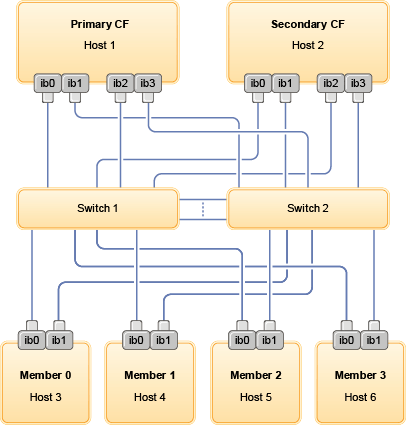
Figure 2. The 2 CFs and
four members connect to two switches.
Configurations without multiple communication
adapter ports
The
following section is for illustration purposes. Configurations without
multiple communication adapter ports do not offer redundancy on the
switch.
In DB2 pureScale environments
without multiple communication adapter
ports, all member and CF communication adapter ports must be
on the same subnet. As additional members are added, more CF resources
are required to handle the members requests. If the number or amount
of time members wait for CFs as
members are added start to affect service level agreements of applications,
consider adopting a multiple communication
adapter ports topology.
The following table contains an
example network topology of a
DB2 pureScale environment
with a single
communication adapter
port to each
CF and member.
Table 3. Single communication adapter port with 1
switch| Host |
Cluster interconnect adapter |
Adap-ter port |
Network interface name |
Cluster interconnect netname |
IP address |
Subnetwork mask (Netmask) |
Subnet |
|---|
| PrimaryCF |
iba0 |
0 |
ib0 |
PrimaryCF-netname1 |
10.123.0.1 |
255.255.255.0 |
10.123.0.0 |
| SecondaryCF |
iba0 |
0 |
ib0 |
SecondaryCF-netname1 |
10.123.0.2 |
255.255.255.0 |
10.123.0.0 |
| Member0 |
iba0 |
0 |
ib0 |
Member0-netname |
10.123.0.101 |
255.255.255.0 |
10.123.0.0 |
| Member1 |
iba0 |
0 |
ib0 |
Member1-netname |
10.123.0.102 |
255.255.255.0 |
10.123.0.0 |
| Member2 |
iba0 |
0 |
ib0 |
Member2-netname |
10.123.0.103 |
255.255.255.0 |
10.123.0.0 |
| Member3 |
iba0 |
0 |
ib0 |
Member3-netname |
10.123.0.104 |
255.255.255.0 |
10.123.0.0 |
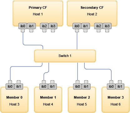
Figure 3. The 2 CFs and
four members connect to one switch.


