Troubleshooting
Problem
This document outlines the setup of an IBM i Host and IBM i Guest using Ethernet Bridging.
Resolving The Problem
| Important Note: Ethernet Bridging requires the host system to be at a release of 7.1 or greater |
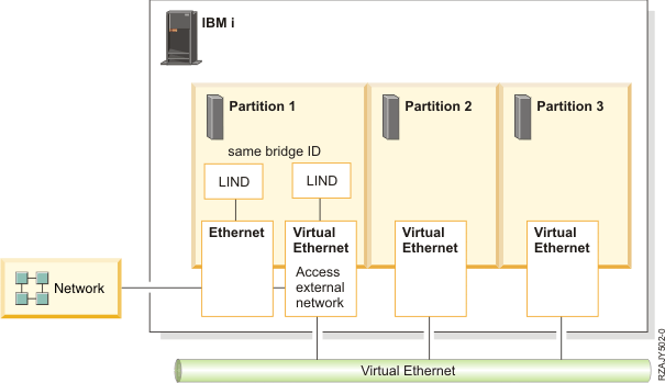
Using layer-2 bridging, one Ethernet port in an IBM i partition can provide network access for other logical partitions on the same platform. Layer-2 bridging functions similar to the Shared Ethernet Adapter (SEA) support provided by a Power Systems Virtual I/O Server (VIOS) partition.
Layer-2 bridging works by putting one physical and one virtual Ethernet adapter into a mode where they can receive traffic that is not destined for their address. This traffic is selectively sent onto the other network according to the IEEE 802.1D standard, known as bridging the frames. Frames transmitted by virtual Ethernet adapters on the same VLAN as the bridging virtual Ethernet adapter can be sent to the physical network. Frames sent from the physical network can be received by adapters on the virtual network.

IBM suggests that the selected Ethernet resources be used for only layer-2 bridging and not for IBM i TCP/IP configuration. There is a significant increase in processor usage for any host traffic that uses bridged resources.
In addition, any line description that is used for bridging receives many frames that are not useful to the TCP/IP stack. These frames use unnecessary processing resources.
Preparing for Ethernet Layer-2 Bridging
You should take the following steps to prepare for Ethernet Layer-2 Bridging configuration:
| 1. | Select a physical Ethernet resource to use for layer-2 bridging. Any Ethernet resource that supports line speeds of 1 Gbps or greater is supported, except for Host Ethernet Adapter (HEA) resources. HEA already supports the ability for multiple partitions to use a single physical port by assigning each partition a logical port. For information about using a HEA resource, see the Configuring Host Ethernet Adapter topic collection in the IBM Power Systems Hardware Information Center. The Ethernet resource must not be in use by any varied-on line description, LAN console, or remote support. An aggregate line description can also be used to bridge traffic to the external network. |
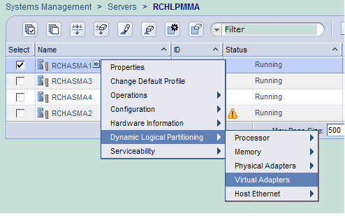
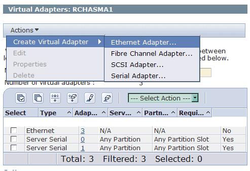
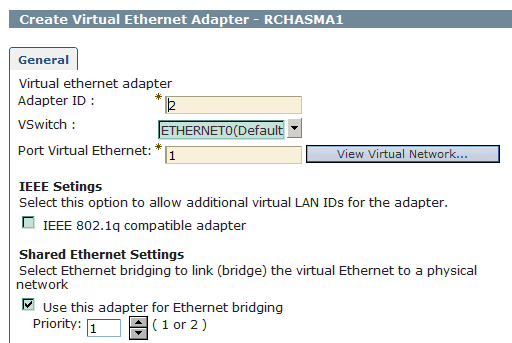
| 2. | Create a virtual Ethernet resource to use for layer-2 bridging and record its resource name. See Rochester Support Center Knowledgebase document New, Adding a Virtual Ethernet (F/C268C) on HMC V7 or Higher: If using a Hardware Management Console, create a virtual Ethernet adapter for the desired VLAN ID. Check the "Access external network" box to indicate that this virtual Ethernet adapter is used to bridge traffic to the physical network. Note: On later versions of the HMC, the parameter reads Use this adapter for bridging box. If using the IBM i Virtual Partition Manager, the virtual Ethernet adapter is automatically created with the ability to access the external network. |
| 3. | Choose an alphanumeric name, a maximum of 10 characters, for the bridge itself. You should make the name unique from any existing bridge names. |
On Guest (Secondary Partition)
| 1. | Use the same steps as above to create the virtual resource on the Guest partition, verifying that it has the same Port Virtual Ethernet ID as the Host partition with one exception. Note: Do not select Use this adapter for Ethernet bridging. |
| 2. | Create the Ethernet line on new virtual resource created on the guest LPAR: CRTLINETH LIND(VETHLINE) RSRCNAME(CMNxx) Note: On the this line, we do not use a BridgeID because the Guest partition finds the virtual resource on the Host partition through the Port Virtual Ethernet ID (vlan ID). |
| 3. | Vary on Ethernet line and assign TCP/IP interfaces as normal. |
TCP/IP Configuration
| Important Note: IBM suggests that the selected Ethernet resources be used for only layer-2 bridging and not for IBM i TCP/IP configuration. There is a significant increase in processor usage for any host traffic that uses bridged resources. In addition, any line description that is used for bridging receives many frames that are not useful to the TCP/IP stack. These frames use unnecessary processing resources. The virtual Ethernet line on the host does not require an interface. You only need the physical and virtual lines active for the bridge function to work. You should not have an interface on the physical line used for the bridge either. Create a separate physical line & interface for network traffic on the Host. |
Create your TCP/IP interfaces as though you're treating each IP address as a host on the logical network. Using an example network of 192.168.10.x (subnet mask 255.255.255.0), each of the interfaces involved will have the same 255.255.255.0 mask. Additionally, the *DFTROUTE on each system should point to the network gateway (example: 192.168.10.254). On the host partition, a separate physical line outside the bridge functionality should be created for the TCP/IP configuration
Example TCP/IP Configuration:
Partition 1 | Partition 2 | Partition 3 |
| Physical Line = PHYS2 / IP Address = 192.168.10.1 (255.255.255.0) | Virtual Line = VIRT / IP Address = 192.168.10.2 (255.255.255.0) | Virtual Line = VIRT / IP Address = 192.168.10.3 (255.255.255.0) |
| *DFTROUTE next hop = 192.168.10.254 | *DFTROUTE next hop = 192.168.10.254 | *DFTROUTE next hop = 192.168.10.254 |
Managing Ethernet Layer-2 Bridging
While an Ethernet line description is varied off, its Bridge identifier (BRIDGE) can be changed to a different name. To indicate the line description is not used for bridging, you should specify *NONE.
In IBM i 7.1, a bridge identifier for an Ethernet line description is not visible from DSPLIND. Use the CHGLINETH command and prompt to see the Bridge identifier for an Ethernet line description.
A communications trace (managed by the STRCMNTRC, ENDCMNTRC, PRTCMNTRC, and DLTCMNTRC commands) traces each incoming and outgoing frame for the selected line description. Each traced incoming frame was bridged, handled by IBM i TCP/IP, or discarded. An outgoing frame was sent by the TCP/IP stack or bridged from the other network.
Notes:
1. The bridge ID is only necessary on the Host Partition; it is not required on the virtual Ethernet line(s) configured within the Guest Partitions.
2. Console access is controlled by the functionality of the Ethernet bridge.
3. Guest partitions can share the 268C Ethernet resource used by the console, as well as the (virtual) Ethernet line for external access through the bridge.
4. Refer to Red Paper Creating IBM i Client Partitions Using Virtual Partition Manager at the following URL:http://www.redbooks.ibm.com/abstracts/redp4806.html?Open
Historical Number
622246891
Was this topic helpful?
Document Information
Modified date:
18 December 2019
UID
nas8N1011193


